From Amatérské Radio magazine, issue 1/89. By Milan Prazan and Jaromir Mynarik.
Original English translation by Marek Bartoň.
This document is a work in progress.
CONTENTS
- Personal Microcomputers
- ZX Spectrum Architecture
- Personal Microcomputer MISTRUM
- Description of the microcomputer wiring
- Software Fit-Out
- Construction
- MISTRUM Peripheral - Light Pen
- BIBLIOGRAPHY
PERSONAL MICROCOMPUTERS
The current era can be characterised by the introduction of microelectronics into the majority of segments of our national economy. These developments which have proven inevitable, are in this country somewhat delayed compared to the rest of the world. Nevertheless, an effort by the majority of our microelectronic manufacturers is trying to rectify this situation as much as possible, by making use of their own resources rather than by purchasing foreign equipment - foreign currency reserves are always in short supply. Most of the development problems nevertheless arise due to insufficient supply of basic electronic component parts. At the same time, the import of modern electronic circuits, at least from the Communist Bloc countries and in particular from the USSR, is not resolved satisfactorily. For these reasons, Czechoslovak electronic appliances are either unnecessarily complex and therefore expensive and unreliable or the electronic component needs are met by technology imports from the Capitalist countries.
Since the introduction of microelectronics in this country, one of the topics has been the spread of microcomputers into the households. A big thanks for the popularity of microcomputers goes to entertainment programs - games, which in an enjoyable and unforced manner have acquainted with electronics even individuals who were otherwise computer illiterate or suspicious of computer technology.
The main factors in establishing home computers are their cost and software availability. There is plenty of awareness of these two requirements overseas and thus foreign companies put a lot of effort to address these matters. This is reflected in this country by the fact that the most popular home computer makes are the various Sinclair company models. These computers became popular particularly due to their low purchase price as well as wide software availability, without which, even the best hardware is found lacking.
The Sinclair computer line-up started with the ZX80 model in the year 1980 and was soon supplanted by the ZX81. It needs to be emphasised that the popularity of these models was amplified particularly by their low purchase price. The low price was achieved especially by an optimal computer design and by the use of the most modern (at the time) component parts as well as by the simplicity of the circuit itself. Sinclair company’s pricing structure also had an effect on unit cost.
In 1982 the company introduced to the market a new computer model by the name of Sinclair Spectrum. In comparison to their previous models, the new Spectrum was an improved type, sporting larger memory, bigger software base, “colour” connection to a colour television, keyboard etc..
The new model had however retained the same basic characteristics common to its predecessors, such as the elegant electronic design and low cost. The new computer model had quickly replaced its predecessors and soon became the best selling model in the whole of Western Europe. Similar situation occurred in this country - the ZX Spectrum was privately imported in such numbers that it has become a de-facto standard, all thanks to its low price. It’s popularity was noted so much so that a “few units” were imported by the official government import and sale agency PZO Tuzex. Similarly, other retail outlets made available for sale a computer by the name of Delta, which was a copy of the Sinclair Spectrum Plus. It should be noted however, that the quantities on offer by these retail outlets were nowhere near enough to satisfy the customer demand.
Attempts to rectify this lack of availability of Sinclair microcomputers have been made by such enterprises as the SLUZBA co-operative - Skalica, which began the manufacture of the Didaktic Gama microcomputer. This model is software compatible with the ZX Spectrum line and what’s more, it has some significant improvements over its predecessors, such as a better keyboard. The manufacturer should note, that the retail price it set for this model is finally in the ball-park to make it likely to become a good seller.
In overseas markets, the ZX Spectrum has been supplanted by compatible models ZX Spectrum Plus, Plus 2 and Plus 3 as well as ZX Spectrum 128. All these variants are software compatible with the original ZX Spectrum microcomputer.
From the above it can be seen that companies abroad give significance to making their newly developed and marketed models compatible with existing extensive software base. It is a shame that this fact is overlooked by the companies involved in the development of microcomputers in this country (e.g. PMD-85, ONDRA), especially given their lacklustre efforts in software development and distribution. In particular, software development is in chaos and this lack of coordination splinters the nation’s coding abilities.
The spread of ZX Spectrum microcomputers in this country has to some extent standardised the microprocessor arena, at least in households. In some instances individuals even use these small computer appliances to make their employed work more effective.
This edition of Amateur Radio (Constructor Edition) aims to make available the technical details for constructing a ZX Spectrum type microcomputer to those individuals, who do not wish to look at their computer as some sort of a mysterious “black box”. Another goal was to enlighten the reader as how to arrive at certain technical solutions to realise equivalent electronic circuits in an elegant and simple manner.
The second part of this article shows the design and construction of the Mistrum microcomputer which should help to alleviate the shortage of Spectrum microcomputers in our country as stated previously. At the same time we wish to show how to solve a given problem in a variety of ways with the aim of achieving an optimal design as well as lowering cost while maintaining compatibility. At the same time we understand the need to allow for a certain amount of individual variability during construction of Mistrums, given the chronic component shortages in our country (in particular the large-integration circuits such as the LS range or perhaps ALS).
Mistrum microcomputer is aimed predominately for amateur construction and it is thus assumed that the abilities and means of various individuals vary and thus a given constructor will modify the presented design to meet his needs. The aim of this design is simply to allow a constructor to make his own ZX Spectrum compatible microcomputer, given the extent of available software in this country. It is commonly accepted, that most microprocessor owners are driven by some amount of zeal and resourcefulness and thus acquiring software for the machine should not be a problem in practice (mostly).
For completeness it needs to be mentioned that the presented Mistrum microcomputer design has been presented to SLUZBA co-operative - Skalica as an improved circuit over their Didaktik Gama design effort - their design requires costly imports of foreign sourced components. Let’s hope that in the future we will see them produce an innovative yet improved version of such a microcomputer such as a “Didaktik Gama +4”.
ZX SPECTRUM ARCHITECTURE
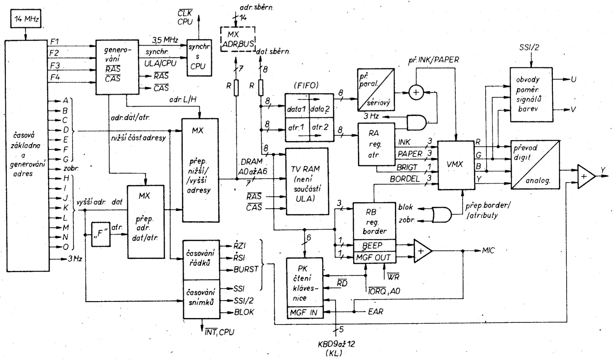
The structure of the 48kB ZX Spectrum microcomputer is shown in block schematic diagram (obr.1), for similar schematic refer to [1]. Part of the microcomputer is designed in the traditional way (CPU, ROM, RAM 32kB, partly TV RAM). The non-traditional aspect of the design is the ULA circuit. This specialised custom integrated circuit manages several important system functions. From the system point of view it represents an autonomous section which functions in parallel with the basic microcomputer section as well as handling synchronisation between the two. It is interesting to note, that to separate (interface?) two distinct buses only resistors are used. Another non-traditional aspect of the design is the bus hand-over during shared access to TV RAM. When this conflict arises, the ULA solves it by pausing the CPU clock.
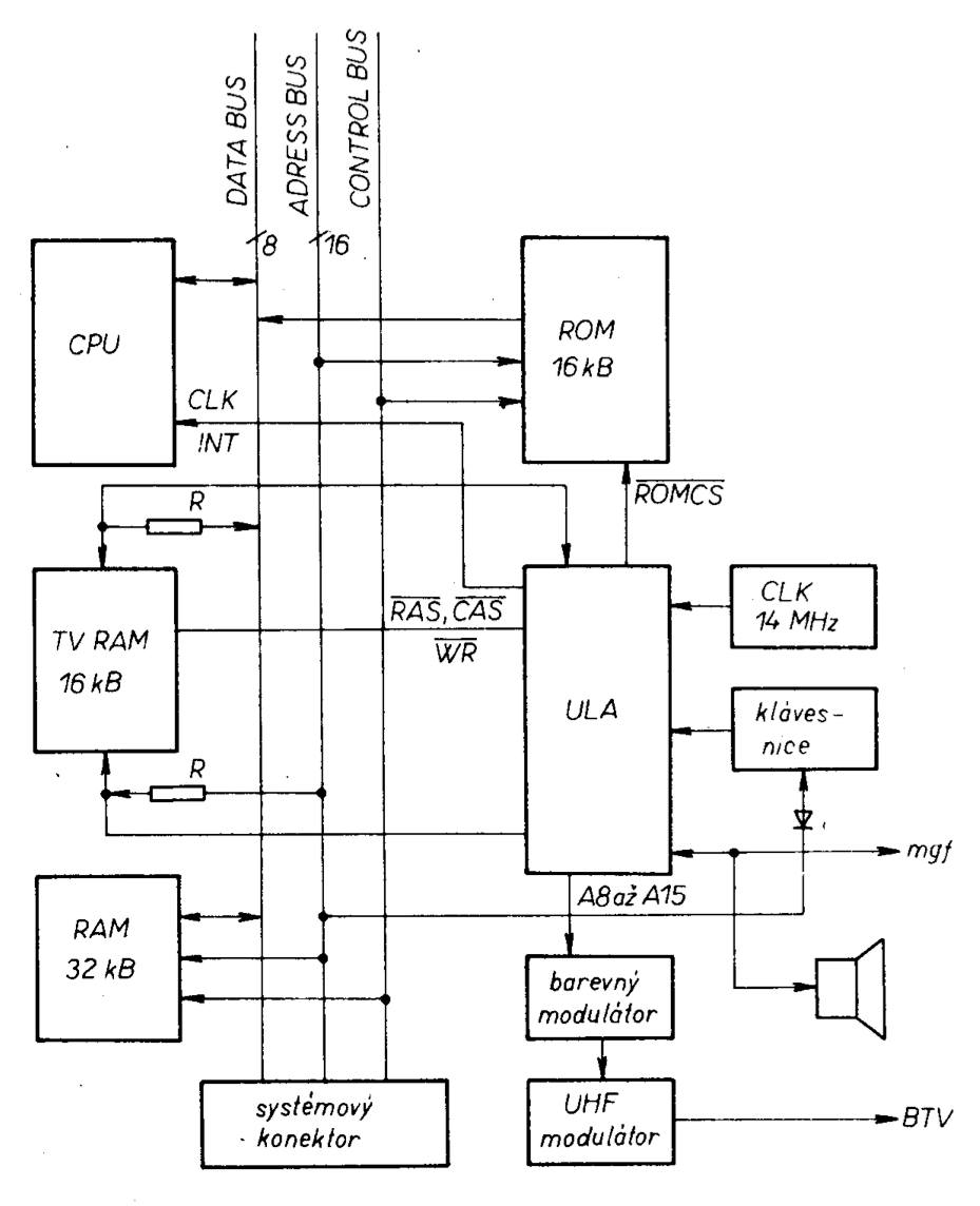
From the block schematic it is apparent that the ULA circuit is responsible for the reading and displaying of data from TV RAM to the TV receiver. The displayed data consists of raster graphics with a resolution of 256 dots per line and 192 lines. As well as that, it is possible to display an 8 x 8 raster graphic in eight colours for each dot as well as its background. Additionally the ULA manages the display of eight colours in normal as well as in increased brightness mode and it also allows the blinking of the raster. Aside from managing the video display the ULA also interfaces with a QWERTY keyboard, cassette tape and audio output. And lastly the ULA displays a coloured border around the visible video screen. From the block diagram one can see the lengths the designers went to, to simplify the design as much as possible to achieve low manufacturing costs.
Microprocessor
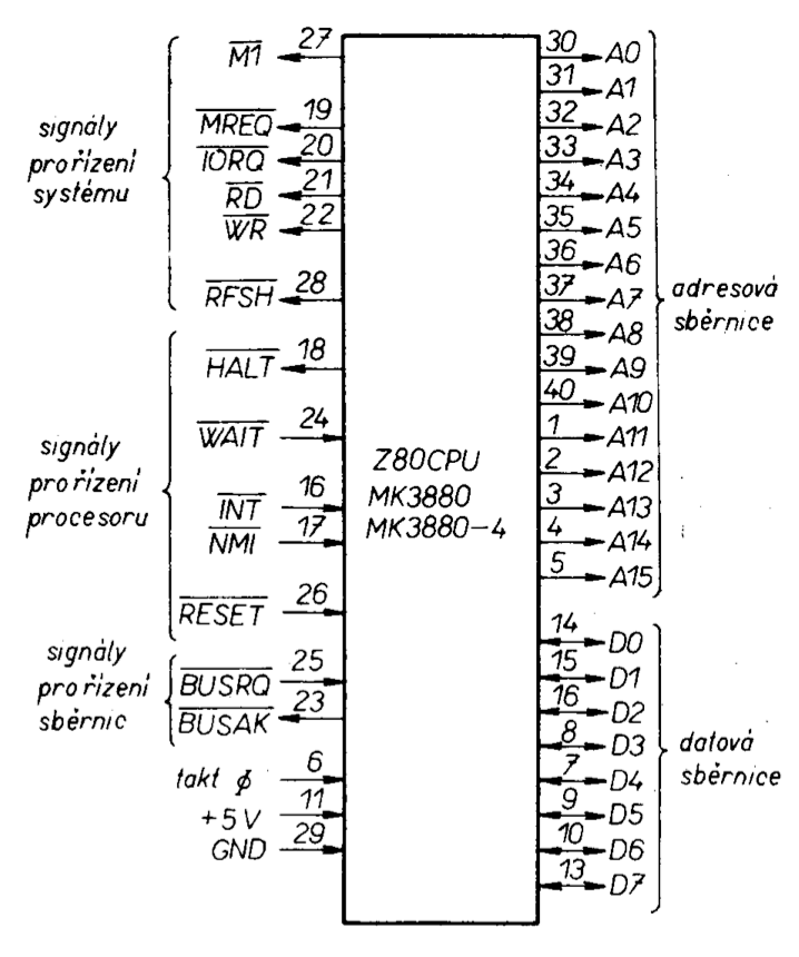
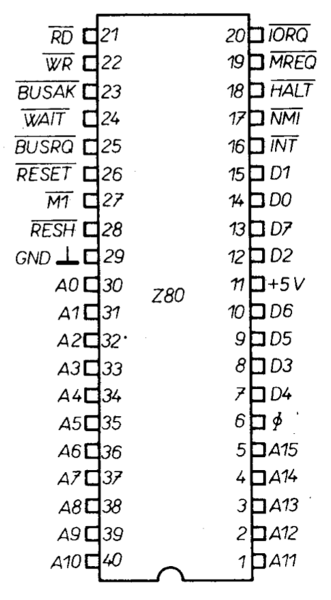
The Spectrum microcomputer uses a popular 8-bit microprocessor (CPU) manufactured by ZILOG, the Z-80A. It runs with a 3.5 MHz clock generated by the ULA circuit subdivided from a 14 MHz clock. (Equivalent Z-80A is fabricated in the German Democratic Republic under the designation UA880D).
The function and connection of the CPU IC is shown in diagrams obr.2 and obr.3. The reader can find additional information in previous editions of AR magazine (eg. in [2]). This edition of AR will cover only such information that is necessary to describe the function of ZX Spectrum and Mistrum microcomputers.
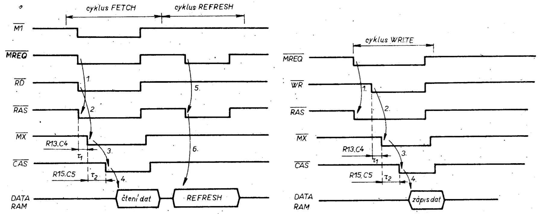
In figure obr.4 we can see the instruction cycle timing and figure obr.5 shows the CPU timing during memory accesses - opcode fetch (cycle M1). Noteworthy, and something we will come back to, is the time instance when signal MREQ rises from L to H during phase T3 compared to figure obr.6 where this (MREQ) signal also rises during a phase labelled T3 but it does so when the clock is LOW.
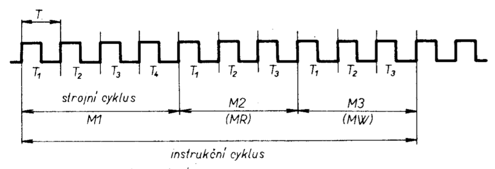
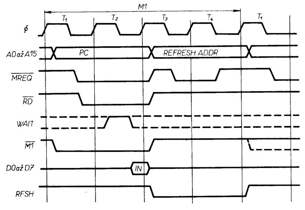
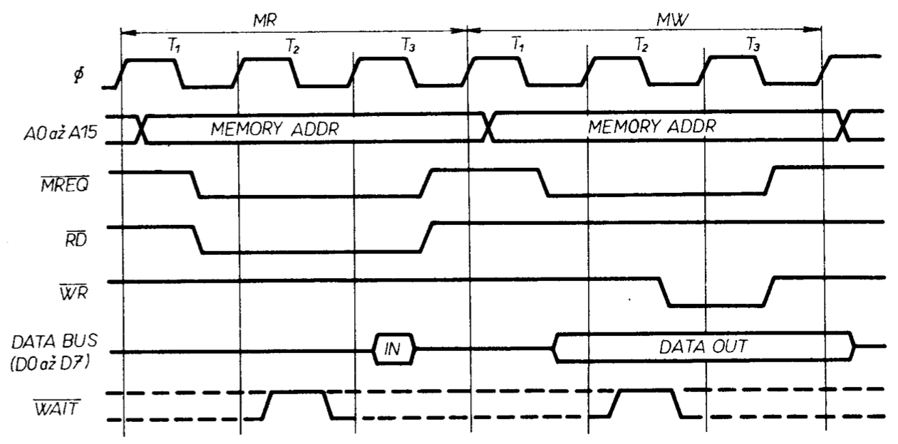
This timing difference allows the ULA to distinguish between the CPU (instruction) opcode fetch and CPU memory read/write. Similarly, we will use figures obr.8 to obr.12 to compare the operating speeds of the ZX Spectrum and Mistrum microcomputers.
(NOTE: obr.8 to obr.12 are tables of Z80 instrunction timings. They have not been reproduced here yet.)
Memory
ROMemory
The 16kB Read Only Memory (ROM) is in the Spectrum located from 0000H to 3FFFH. This address space is determined by the ULA which acts as an address decoder. Signal ROMCS goes through a 680 Ohm resistor to then chip-enable the ROM. This signal is also routed to a ZX Spectrum edge connector to allow to externally disable the ROM. This ROM contains the complete ZX Spectrum operating system inclusive of a BASIC language interpreter; more detailed ROM information can be found in, for instance [3] and [4].
32kB RAMemory
The 32 kb RAM occupies the address space from 8000H to FFFFH. It consists of eight 4532 chips (or equivalents). These are 32768x1 bit memories and are dynamic i.e. they require a periodic row address refresh no slower than every 2 ms.
There has been a lot written about these memories so let us add just a few words on how to connect them up. Address switching is realised in a classical manner using four, two-to-one multiplexers of type 74LS157. More interesting is the method of generating the RAS and CAS control signals for dynamic RAMs. In this connection (see [1]) the RAS signal is generated directly from the MREQ signal. And after a short delay, the multiplexer switchover signal is generated. Should the CPU be in a memory read/write cycle then the CPU will generate signals RD/WR and the 32 kB RAM will be accessed, thus A15 = 1. After switching the multiplexer, a CAS signal is generated by the sum of the circuit to write the second half (MSB) of the address.
If the CPU is in a refresh cycle, only the MREQ signal is asserted without the RD/WR signals and only the refresh address will be written by the RAS signal. From the above, one can see that the microprocessor output pin RFSH intended just for this purpose is superfluous!
TV RAM
This memory is realised by eight 4116/120ns chips. It is addressed by the ULA from 4000H to 7FFFH. Part of the memory (6912 bytes) contains the DISPLAY FILE (the part displayed on a TV screen), another part contains system variables and the rest of the memory is designated for use by the BASIC interpreter.
This memory is shared between the Microprocessor and the ULA. The CPU treats the TV RAM as just an ordinary RAM. The ULA will fetch from this memory (from part of this memory) data that were there previously stored by the CPU and will display this data on a TV screen. This video data is displayed in a 256x192 point raster i.e. 32 characters by 24 rows in an 8x8 point raster. Each 8 points on the TV have a fixed address in TV RAM.
Each 8x8 field corresponds to one attributes physical address. It is possible to divide the TV field into 3 areas: top third - rows 0 to 7, middle third - rows 8 to 15 and bottom third - rows 16 to 23. This division into thirds directly correlates to specific addresses in TV RAM, see further. Figure obr.13 shows the character field displayed on a TV receiver divided into thirds. Each character in this field comprises eight TV lines (eight scan-lines of the cathode ray).
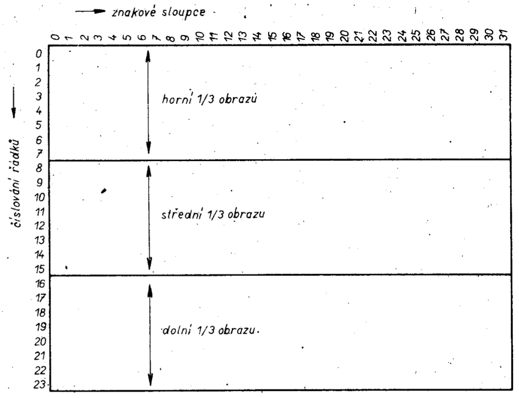
Figure obr.14 shows the address allocation per each eight bit set including its attribute. Also evident is the relationship of addresses to screen thirds. One third of the TV screen contains 2048 DISPLAY FILE bytes; the attribute field contains 768 bytes for the whole screen.
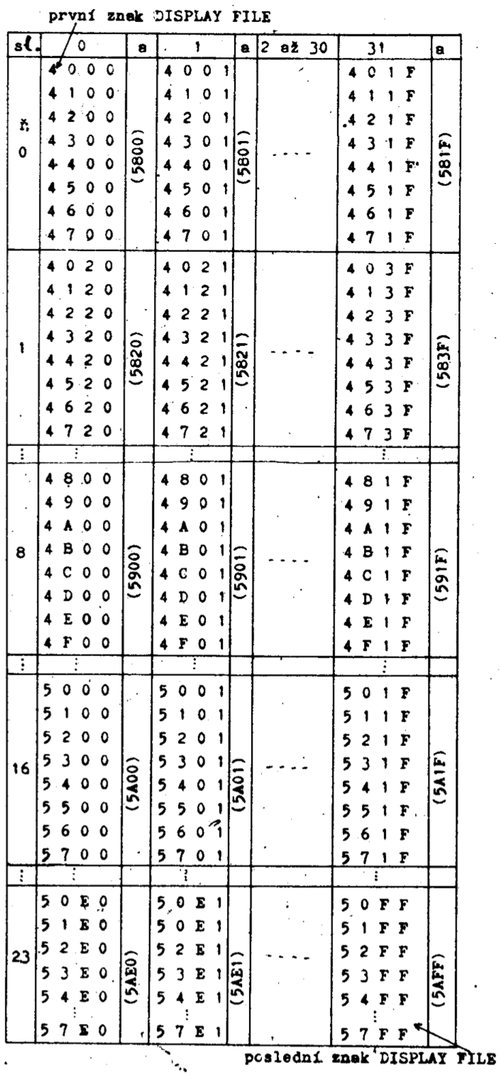
The attribute addresses are in figure obr.14 given in parentheses and always apply to the 8 bytes (in the character context it is 64 points). The TV addressing method is apparent during the loading of a splash screen from tape when each 8 point group is addressed in ascending sequence with the attributes loaded last – attributes carrying the colour information for the already displayed data.
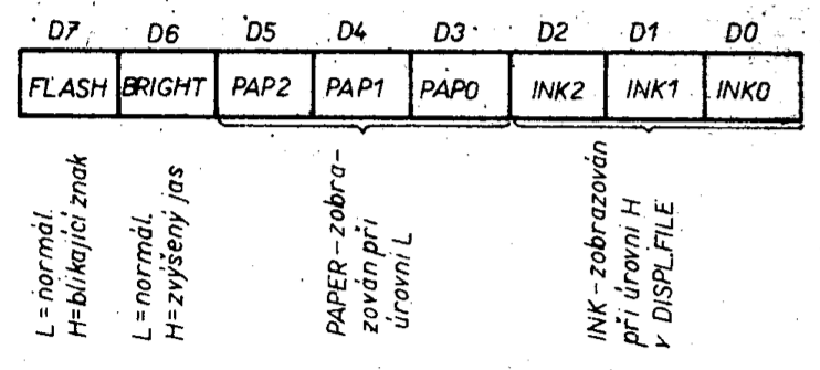
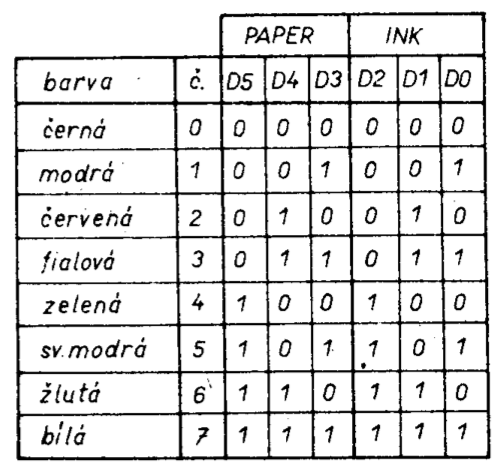
With this 32 character per row and 24 rows on the screen organisation, one gets 32x24x(8+1) x 6912 bytes (each character comprises eight bytes and one attribute). Each character on the screen can be assigned two colours from a range of eight colours; one colour is the lit point (INK) and the other colour is the background (PAPER). Furthermore it is possible for each character to choose either a normal brightness or increased brightness (BRIGHT) or to set the whole character blinking (FLASH).
The attribute properties are listed in figure obr.15. From the above it is evident that each character comprises eight data bytes and one attribute byte. When displaying the data byte the most significant bit is displayed first.
The relationship between the display data bytes and the attribute byte is not accidental but is well thought out. Character rows are addressed such that it is as if 8 rows are “side by side” (i.e. it makes it a single row 256 characters wide). Then the addressing of individual data bytes can sequentially increase along “lines” of notional 3 rows all the way to the end of the DISPLAY FILE, inclusive of the corresponding attributes.
This layout of data and attribute addresses was chosen deliberately to make it easy to address the attributes. When a given data byte is being displayed on a screen (8 points) it is necessary to know, there and then, the current attribute value to be able to “colour in” this display data.
To figure out the actual attribute address one makes use of the relationship between the data and attribute addresses. From figure obr.14 it is evident that for each character displayed on a TV screen corresponds an attribute which shares the lower part of its address with the 8 bytes of the displayed character i.e. the lower address is the same for all.
Similarly, there is a certain relationship with the upper address part - relationship which the ULA makes use of. Figure obr.16 shows the interdependence between the upper addresses of data and attributes. To determine the address to use to access an attribute for a given displayed data byte, all that is necessary is to shift around address bits to their correct place for an attribute address, as per figure obr.16. Attribute address bits A10-A13 are always constant.
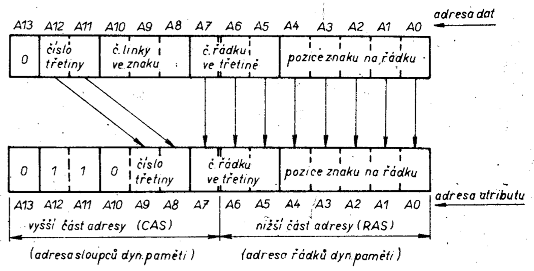
Similarly, individual bits of the data address too, have their significance, and this determines the bytes’ placement on the TV screen.
The meaning/significance of the individual data address bits is:
- addresses A0 to A4 designate the characters’ placement along the row,
- addresses A8 to A10 designate the line number in the character (a character comprises eight scan-lines),
- addresses A5 to A7 determine the row number in the currently accessed screen third (each third contains eight rows),
- addresses A11 and A12 determine the screen third to use (numbered from zero and starting at the top, going down).
With this arrangement of the data address bits it is possible to specify on the screen an actual physical address of any eight point group and from figure obr.16 determine the corresponding attribute address.
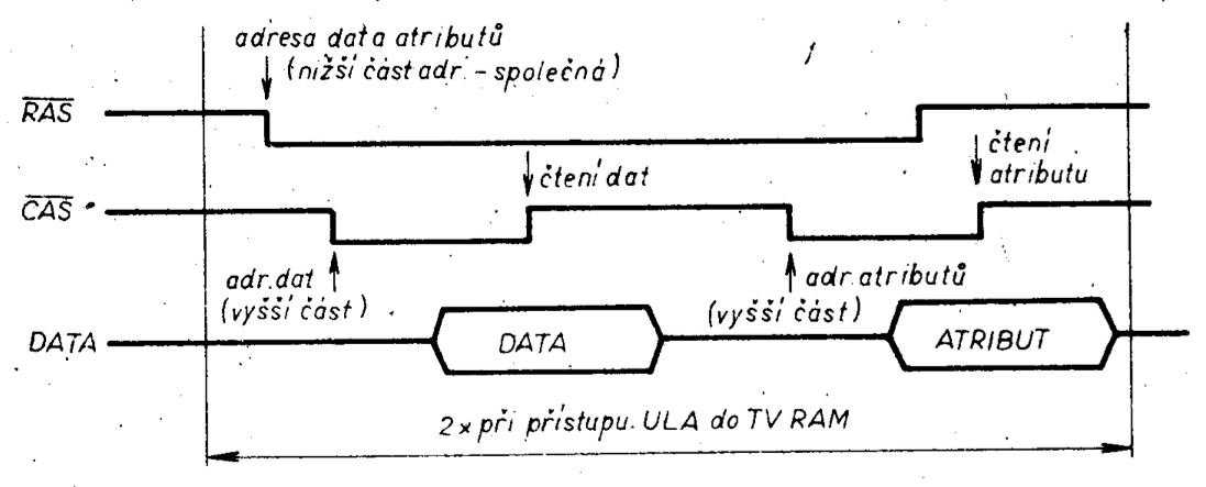
The data address and attribute address relationship is evident from the above. The ULA depends on this relationship when addressing TV RAM in so called page mode, which is often used due to the faster data access thus possible in dynamic rams. The principle on which this paged memory access depends, is based on the fact that the addresses of data to be retrieved from the memory have the same row address, asserted by the RAS signal. (Actually this data access, is access to data from a common row in terms of the actual structure of dynamic memory, whose internal architecture is two-dimensional.)
Then one only needs to perform a single row address write to then be able to sequentially retrieve the memory contents by column address writes utilising the CAS signal.
Figure obr.17 shows the method of data and corresponding attribute retrieval from TV RAM (DISPLAY FILE) by the ULA circuit utilising page mode. Control signals RAS and CAS are generated by the ULA.
ULA
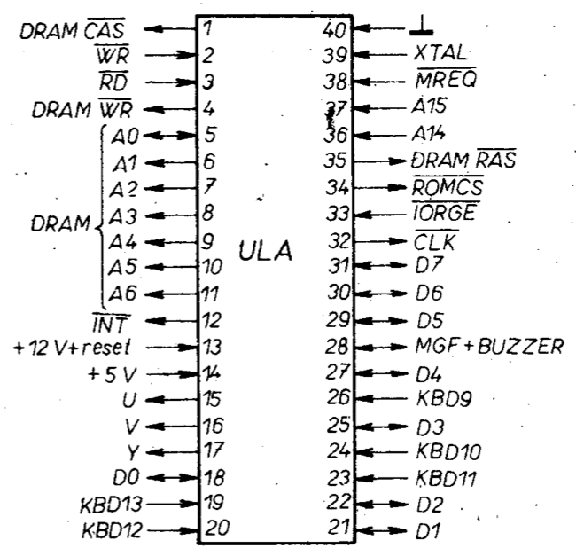
Figure obr.18 shows the pinout of the ULA Application Specific Integrated Circuit (ASIC) which is in a 40 pin DIL package. The functions are as follows:
DRAM A1 to DRAM A6 – are outputs connected to the TV RAM address lines A1 to A6 to access the DISPLAY FILE data and attributes. They are also connected through 330 Ohm resistors to address multiplexers’ outputs. These resistors function as CPU and ULA address bus isolators during the various modes (such as CPU interpreting program from ROM, ULA retrieving the contents of DISPLAY FILE).
DRAM A0 – bidirectional; has the same function as DRAM A1 to DRAM A6 but on top of that it is also used during input/output operations as an ULA enable signal together with the IORQ signal.
D0 to D7 – bidirectional; connected to the TV RAM data bus and, through 470 Ohm resistors, to the microprocessor data bus. These are used to transfer information from the DISPLAY FILE to the ULA during colour information TV display or to transfer data from the microprocessor to ULA output ports (such as changing the border colour - BORDER, output to cassette tape or output to the loudspeaker). Additionally they are used during ULA to microprocessor data transfers (such as input from cassette tape or keyboard reading). And again, the resistors function as data bus separators.
DRAM /RAS – output; used to write the row address (lowest part) to the dynamic TV RAM. This signal is generated during ULA data retrieval (only once) or during microprocessor memory accesses.
In older iterations of the ZX Spectrum hardware this signal was additionally connected via a 330 Ohm resistor to the microprocessor RFSH signal (so that a refresh would be generated during the frame synchronisation impulse, when the ULA is not active with display). Newer ZX Spectrum units do not have this resistor since the dynamic memories are able to retain their contents even during the instant of frame sync impulse. (When it comes to saving costs the Sinclair company is exceptionally thorough!).
ROM CS – output, used to enable the ROM. The ULA functions as an address decoder. This signal is routed to the ROM via a 680 Ohm resistor and is also routed to the edge connector (this allows for disabling the ROM externally).
IORQGE – input, used by the ULA to interface with the microprocessor during input/output instructions. It is connected via a 680 Ohm resistor to the microprocessor IORQ signal. Both signals are routed to the edge connector, IORQGE, to allow blocking (disabling) of the ULA.
KBD9 to KBD13 – inputs, used to read the keyboard. These are through the ULA connected to the data bus in the order D4 to D0. These inputs are connected to +5V through 10 kiloOhm resistors to define state H when a key isn’t pressed.
U – output; the blue-yellow colour ratio output; more details will be provided in the “Colour Modulator” part of this article.
V – the red-yellow colour ratio output
Y – the brightness (intensity) components of the TV signal together with synchronisation stream.
CLK – the output of an approximately 3.5 MHz clocking signal to the CPU (the ULA derives this frequency by dividing the 14 MHz master frequency and pauses this clock at level L when the TV RAM access demands by the CPU and ULA clash). This signal is inverted before being applied to the CPU.
WR – input, which notifies the ULA that the CPU is performing a write operation. Depending on the state of other control signals (MREQ, A14, A15) either signal DRAM WR is generated or data is written into ULA’s internal registers during on OUT instruction together with activity from signals IORQ, A0 (BORDER, SAVE, BEEP). The signal also informs ULA that (when the CPU has been allowed TV RAM access) the CPU has finished the TV RAM write.
DRAM WR – output, used for TV RAM writes.
RD – input, which informs the ULA that the CPU wishes to read data. This CPU to TV RAM access is allowed depending on the state of other control signals (MREQ, A14, A15) and provided that ULA itself doesn’t need to access this memory. When signals IORQ & A0 are asserted, the ULA acts as an input port provided that the DISPLAY FILE is not being read. During input instructions the CPU will bring in inputs KBD9 to KBD13 on D4 to D0 and input from the cassette tape on D6.
MREQ – input, alerting the ULA that a CPU memory cycle is in progress.
INT – output, which generates a 9.2 microSecond interrupt impulse of logic L. This pulse is generated simultaneously with the frame synchronisation pulse, i.e. 50 x per second. The CPU is set to an interrupt mode IM1 and thus doesn’t require an interrupt vector. For CPU operation in IM2 mode the interrupt vector is achieved by eight 10 kiloOhm resistors connected to the CPUs’ data bus and +5v (gives 55H vector).
The INT signal is isolated from the CPU by a 680 Ohm resistor and then routed to the edge connector to allow for external disabling of ULA interrupts.
XTAL – input, used to connect a 14 MHz crystal.
Mgf + BUZZER – bidirectional line, serves as a cassette tape input/output and also for output to the built-in loudspeaker.
The loudspeaker is connected to this pin via two series connected diodes - forward bias direction. When the CPU performs an output operation, the ULA will drive bit D3 to a 0.75 Volt level (for logic D3X0) and to 1.3 Volts for logic D3X1.
Bit D3 is used for output to the cassette tape (SAVE) and it’s software that does the parallel-to-serial conversion!! The small voltage differential is not enough for forward bias (to conduct) the diodes and that is why the speaker is not audible during saves to tape. Bit D4 is used to drive the loudspeaker (BEEP) and in this case the ULA will drive it with a voltage of 2.5 Volt higher. The resulting voltage is now sufficient to forward bias the diodes (cause them to conduct).
+12V + reset – ULA power supply rail and ULA power-on reset pin. A circuit reset is necessary to guarantee correct start-up of Johnson counters it contains - counters which take part in generating the RAS and CAS signals.
+5V – supply rail
The ULA circuits’ main responsibility consists of reading data from DISPLAY FILE and then displaying it on a colour TV. To avoid visible video dropouts when the CPU and ULA both try to simultaneously access the DISPLAY FILE yet allow both access, it is necessary to somehow arbitrate this access.
The TV RAM memory is used by the microprocessor and the ULA circuit. The CPU can either fetch opcodes from this RAM or it can read/write data from/to it. The ULA will only ever read data and attribute from this RAM memory for subsequent display on a TV receiver. An access clash occurs when both the ULA and the CPU try to access this memory at the same time and the ULA resolves this conflict by giving itself priority and temporarily pausing the CPU clock, which it only does so for the needed time - i.e. until it (the ULA) has finished its own access. After this, the CPU clock is re-enabled so that the CPU can access this memory. To increase the operating speed of the whole microcomputer system, the ULA circuit contains a cache (FIFO) from which it will read enough data to display 16 TV screen points, i.e. 2 data bytes and 2 attribute bytes.
The ULA circuit also keeps track of whether the CPU is about to start a memory read/write cycle or cycle M1.
For the read/write cycle the CPU needs 3 clocks and for the M1 cycle it needs 4 clocks, of which 2 clocks are for memory access and 2 clocks are for refresh. However during ULAs’ operation the TV RAM refresh is done automatically (by the ULA) and so it is counterproductive to unnecessarily “retard” the CPU speed. For this reason, during refresh in time M1, the CPU clock is enabled.
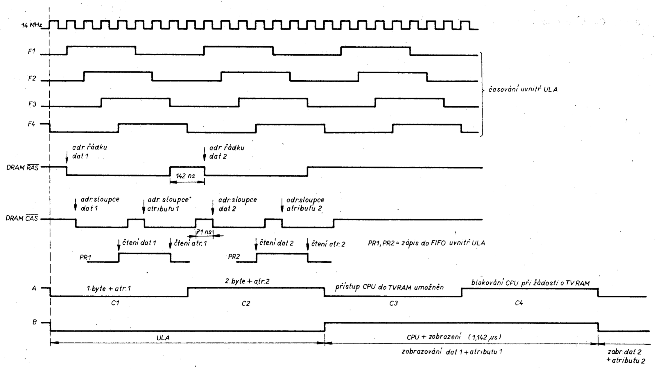
Figure obr.19 shows the ULA timing diagram for reading into its FIFO cache two data bytes and two attribute bytes. It also delineates the time when the CPU is allowed access to TV RAM.
The actual engineering solution of the ULA circuit i.e. its logic circuitry is obviously unknown to us. The subsequent description is only a hypothesis which we arrived at on the basis of analysing the functioning of the ULA IC and by measuring electrical quantities and verifying the function of equivalent circuitry. The actual realisation of an ULA circuit, as we will see, can vary.
ULA activity repeats periodically during TV line display in time C1 to C4. Periods C1 & C2 are reserved for ULA’s memory access; time C2 is to receive a CPU request for TV RAM access and period C4 is reserved for the CPU to finish reading or writing from/to TV RAM.
If a CPU memory access request arrives during times C1, C2 or C4, the CPU clock will be paused until the start of the C3 time. If an M1 cycle were initiated during the middle or towards the end of cycle C3, the CPU would not have enough time to complete this operation (M1) prior to arrival of the next C1 cycle. For this reason, the CPU clock will not be paused during C1 in this instance.
By this time the CPU has already fetched an opcode and refresh is underway so it doesn’t need TV RAM now. The refresh is performed continually by the ULA during data reads.
The ULA commences its activity on TV RAM 1142 microSeconds before the start of output to the TV screen. During phase C1 and phase C2 it will pause the CPU clock if it is itself accessing TV RAM and will fetch 4 bytes into its own FIFO memory (2 data and 2 attribute bytes). During phases C3 and C4 it will commence the displaying of the first data byte inclusive of the first attribute and at the same time it will free the CPU to access TV RAM - should the CPU wish to do so. This will display on the TV screen 8 coloured points side by side with the MSB (most significant bit) up first. In the next cycle again in phases C1 and C2 are subsequent 4 bytes read-in and simultaneously the second byte with second attribute from the previous read are being displayed on the screen. During a single TV row these cycles repeat 32 times, i.e. 36,571 microSeconds. The remaining time (up to 64 uS, which is the length of a single TV row) is used to generate row synchronisation and blanking impulses, see figure obr.20, and for the left border (LB) ahead of the displayed data and for the right border (RB) of the TV screen.
It needs to be said that the colour screen border (BORDER) has nothing to do with TV RAM data or attribute fetches at all (see later). From the above it is evident that the speed demands made on the TV RAM memory are rather high (571ns has to be sufficient to supply 4 bytes inclusive of all memory set-up times, precharge, latency, trailing times etc.)
For this reason the memory chips chosen for this TV RAM are usually 4116/120ns. In figure obr.21 we see the basic block diagram of the ULA circuitry. We start with the time-base where all clocking/timing lines are generated and which also generates the lines for the internal address bus for addressing the TV RAM during displaying.
This TV RAM address generation block transforms the display data address (the upper part of this address) into a part of the attribute address and simultaneously multiplexes the complete address. This address is routed out of the ULA circuit to the address bus DRAM A0 to DRAM A6.
The attribute address generation block is symbolically marked “F”. The data including their attributes are written into the caching FIFO memory. After this, the data are routed to a parallel-to-serial converter, which converts the data byte into its serial form. This serial stream switches/controls the output multiplexer VMX such that level H will “allow through” 3 bits of INK attribute and level L will switch to 3 bit of PAPER attribute – which are stored in cache RA.
From this, one can see that the data stored in TV RAM only carry the attribute for display purposes and do not represent the magnitude of the TV signal as such. From the above it is evident the method which programs make use of to make themselves invisible on the TV screen (for example by disabling the output - program listing of the LIST command by setting the INK and PAPER attributes to the same colour).
Depending on the setting of the colour attributes, level H in TV RAM can be displayed as a point of light or darkness (dot). The colour interpretation is given by the table in figure obr.22 which states the colour shades for INK and PAPER corresponding to the attribute bits, see fig. obr.15.
For the flash function, the display hardware keeps swapping over the INK and PAPER attributes. Attribute bit D7 determines whether the displayed character will blink (level H) or not (level L).
If FLASH = H the ULA will keep inverting (toggling) the serial data stream of the output multiplexer (signal INK/PAP) with a frequency of about 3 Hz. All that does is switch over the INK and PAPER attributes at this switching frequency. This toggle function - an inverter with a control gate - is symbolised in the block scheme as modulo-2 logical OR.
Bit D6 is the carrier of the increased brightness information (BRIGHT) of the currently displayed byte. Level L denotes normal brightness, level H will increase the brightness of the 8-colour palette (except for black).
The output of multiplexer VMX also routes out one more item of information and that is the three bits of the RB register which carry the colour information for the TV screen border (BORDER). These information bits are written into register RB by the ULA at the time when it co-operates with the CPU as an output port. The BORDER colours use the same bit codes - are coded using the same colour palette as PAPER and INK except that one can not use program means to increase the border brightness. The BORDER information bits are outputted on lines D0 to D2 from the CPU when it is executing the OUT 0FEH,A instruction. In this instance the ULA circuit is treated as a port and is selected by the CPU’s A0 pin being Low.
The ZX Spectrum uses linear addressing that is active Low. For the ULA circuit is reserved line A0, line A2 is reserved when connecting a printer and other lines A3 to A6 are reserved for other peripherals (e.g. INTERFACE). When the machine is fully connected up, the only free line is A7. If one uses only a solitary ZX Spectrum then one can make use of lines A1 to A7 (and perhaps A8 to A15) freely, except for A0 = LOW.
The VMX multiplexer is switched to BORDER/ATTRIBUTE during display time by signal BORD/ATR which is generated from signals “blok” and “zobr”.
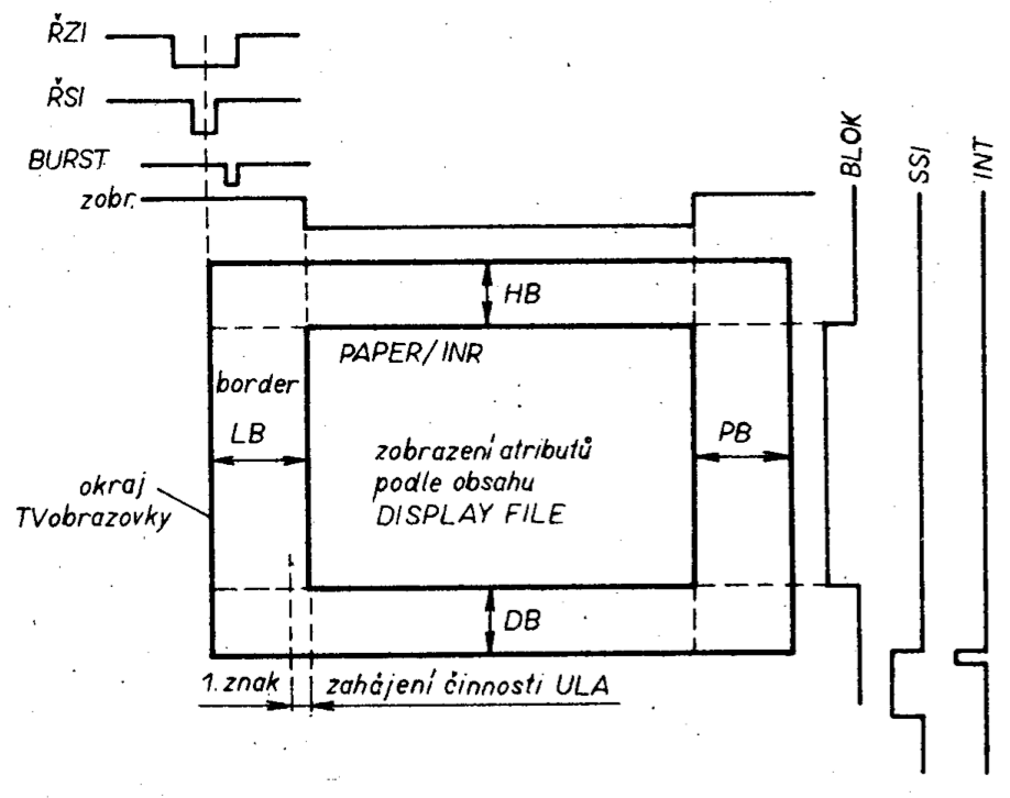
Figure obr.20 shows the timing diagram of these signals. The “zobr” signal is generated by the ULA timebase and it determines the extent of displayed data in the horizontal dimension.
In a similar manner, the “blok” signal determines the dimension of the vertical area. During the time when “zobr” = H and “blok” = H the TV screen is displaying the BORDER. The time designated in Fig. obr.20 as HB marks the travel of 64 TV lines during which the ULA does not display data (and therefore does not work with TV RAM).
Time DB represents the travel of 60 TV lines; 4 lines are blanked due to the generation of frame synchronisation impulse, SSI. Impulse INT is generated at the same time as SSI which cause the CPU to be interrupted.
The VMX multiplexers’ 4 bits of output (3-bit colour carrying, 1-bit brightness info) are routed into a D/A converter. Here these bits are converted into an analogue form and this signal continues on into a combining junction where synchronisation pulses are added. The output of this junction is routed to ULAs’ Y output.
The colour-carrying signals are also routed to a colour-ratio circuit which derives the U and V signals and makes them available on ULAs output pins. The functioning of this part of the ULA will be described in a separate section (see later).
The ULA circuit also manages the data output to a cassette tape recorder. The tape interface uses bit D3 of the databus where the ULA functions as on output port (same as when controlling the BORDER). The bits to be serially recorded on tape are processed purely by program (software) means. The ULA functions only as a port! The ULA D3 output pin is routed to tape output + BUZZER (see ULA output description) output 28. Here a logic change represents a voltage change from 0.75 to 1.3 volts. This output is simultaneously used for driving the built-in loudspeaker. Bit D4 is used to control the loudspeaker in the same manner as for output to cassette tape except that bit D4 causes a voltage shift of 2.5 volts. Computer sound is again realised purely by software means (such as by interpreting the BEEP command). The input from tape is engineered in a similar manner as output to tape. ULAs’ output pin 28 is used for all three functions (because of limited pins available in the ULA IC package). These are output to tape and loudspeaker as well as input from tape. For this reason pin 28 is bi-directional.
Inside the ULA circuit this pin is connected to a voltage comparator which is connected to data bus bit D6 when the CPU is executing the IN A,0FEH instruction. Processing of the incoming tape data stream is again a software process and its success depends only on the signal quality from the cassette tape deck. At this point we wish to draw the readers attention to a particular characteristic of the functioning of this port.
Given that it is a bi-directional line it is necessary during tape reads to “disconnect” the tape output circuitry (by software means). No doubt many users of the ZX Spectrum have noticed that if they attempt to read from tape straight after resetting the microcomputer, before even the first touch of the keyboard, the sound from the loudspeaker is coming out rather more “quietly” than if a key was pressed first. It is because the output-to-tape circuits are not yet programmatically “disconnected” and they electrically load-down the incoming tape signal. Only after a key on the keyboard is pressed are these programmatically disconnected and the loudspeaker signal/sound has a larger magnitude (for example in the COPY COPY program the output is not handled in such a way and thus it is possible that a program which can “normally” be easily loaded into RAM now cannot be copied and the computer user is baffled!
From the above it is evident why a sufficiently strong signal from the cassette tape deck going into the ZX Spectrum is necessary (the usual tape deck output used for this purpose is either the loudspeaker output or headphone output).
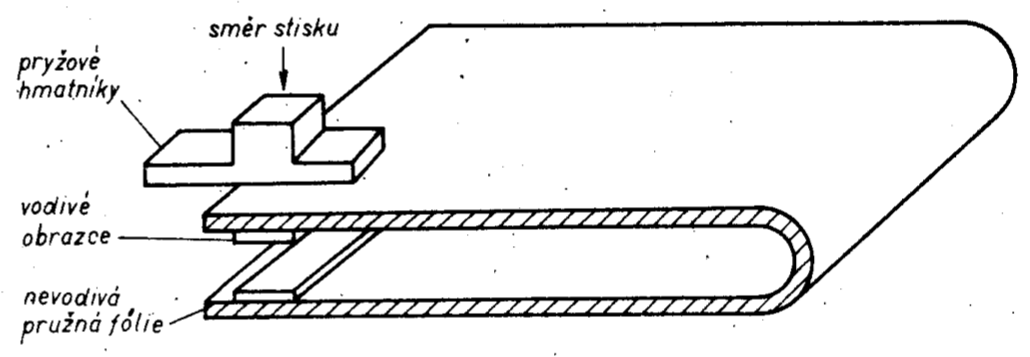
In Figure obr.21 we have block PK which serves to interface the keyboard to the microprocessor. ZX Spectrum uses a QUERTY keyboard layout which comprises a matrix of switches in a 8x5 raster. The switch contacts make use of a flexible metallised membrane (vapour deposited layer of silver on a flexible backing) in a pattern which acts as button contacts. This membrane is bent over itself (figure obr.23) and this creates sufficient tension to cause the keys to spring back after being depressed. Above this membrane (foil) are the actual rubber push button keytops in a matrix configuration which force the membrane surfaces together at a given point and thus complete the electrical circuit for that particular key. The state of the keyboard is monitored by five ULA inputs (KBD9 to 13, Fig. obr.24). These inputs are biased HIGH via a 10 kiloOhm resistor when not active (key not pressed). The remaining 8 lines are connected via diodes to the upper part of the address bus A8 to A15. Each line is activated by program means such that each address line A8 to A15 is sequentially polled by logic level LOW. When a key is depressed the corresponding LOW level propagates to the appropriate KBD line (KBD9 to KBD13). The CPU will determine which key is being pressed by executing a IN A,0FEH instruction through the ULA.
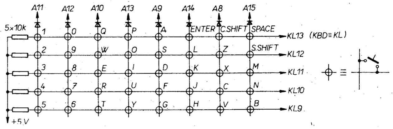
So that the A8 to A15 lines do not mutually affect each other when several keys are pressed at once, they are separated by diodes. The software keyboard read routine makes use of a Z-80 CPU characteristic which is that when the CPU executes an input instruction IN A,addr the upper half of the address bus A8 to A15 will show/manifest the contents of register A while the lower half A0 to A7 will have the address.
In this way one can sequentially drive the keyboard address lines A8 to A15 as needs be. The detection of a press of a given key will require reading 8 times of the keyboard with the A register loaded with a constant such that only one line (A8 to A15) at a time is driven with logic LOW.
If the requirement is to test for the pressing of any key then all one needs to do is load register A with a zero and by a single read of the keyboard using the IN A,0FEH instruction determine if any key has been pressed. In the affirmative case, bits D0 to D4 will contain logic LOW corresponding to the actual key pressed.
The detection of key presses as well as the generation of keywords/tokens is normally decoded by software of the operating system [4].
From the above it is evident that the lifetime of the membrane keyboard is rather short. The number of keypresses available before failure sets in, is primarily dependent on the life of the metallised foil (membrane), that is why it is highly recommended to use one of the controllers (joysticks) either imported from abroad or constructed under hobby conditions (including a suitable interface, for example [5]). It is sad to see that in this era of “thunderous” microelectronic growth in this country, none of the manufacturers have put into production these very essential computer peripherals.
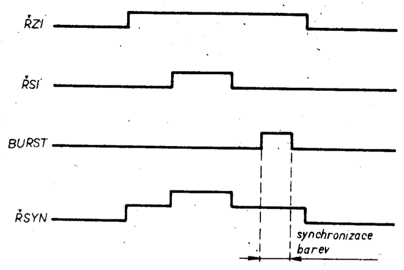
The last part of the ULA circuit are the blocks for generating synchronisation pulses for a TV receiver. Figure obr.25 shows the generation of a blanking (RZI) and line (RSI) synchronisation impulse. These impulses are combined in the ULA’s output video modulator (Fig. obr.21). Signal “burst” is there for chroma signal colour modulator sync.
The complete video signal, as was measured at the input to a UHF modulator, is shown in Fig. obr.27. One can clearly see the time relationship between blanking and line sync pulses inclusive of their voltage levels. The diagram shows one TV line which is displaying the information part of the screen including the BORDER. Symbols LB and PB designate the colour borders, such as in Figure obr.20. Information area INF represents the display of the actual INK and PAPER attribute levels set by the colour shade. In the picture we have also marked (by a dashed line) the level of white during increased brightness (BRIGHTX1). For simplicity and clarity, diagram 27 doesn’t show the 4.436 Mhz colour carrier which is intermodulated with the video signal and corresponds to the colour shade (hue).
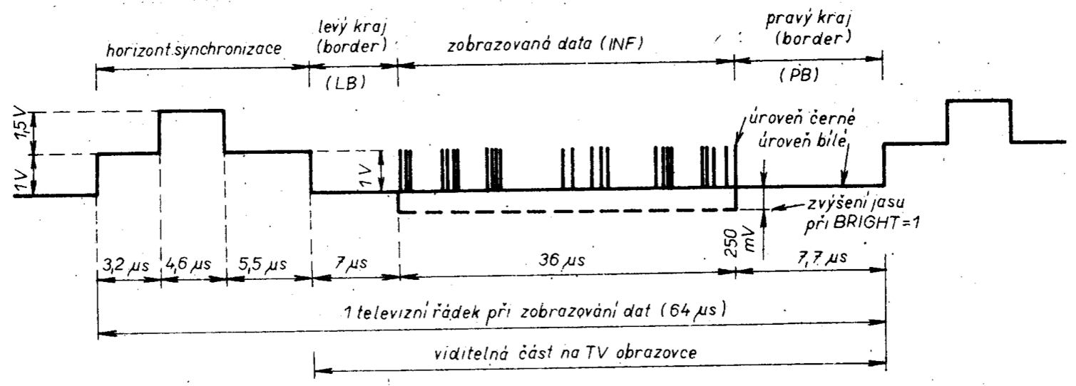
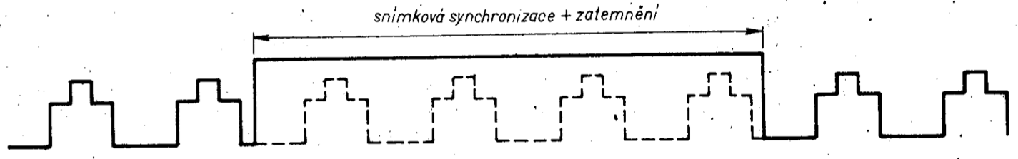
Figure obr.30 shows the synchronisation train of the SSI.
From the above described engineering solution of the ULA circuit one can glance one major shortcoming. To clarify this, lets review a few facts. The ULA communicates with the CPU by means of a control bus and especially the data bus. The data bus is used by the ULA particularly for fetching TV RAM video information from the DISPLAY FILE area. During access contention for this memory, the ULA is prioritised and the CPU clock is paused.
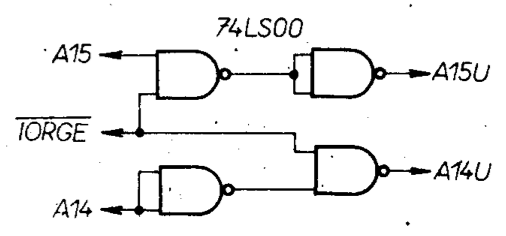
Should the CPU want keyboard state information from the ULA this would also create a data bus collision however, despite the fact that the CPU does not need TV RAM at all. The original ULA circuit designers were aware of this collision possibility and for this reason the keyboard service software routine utilised a maskable interrupt which is initiated 50 times a second by the ULA circuit together with the frame sync pulse. At this time the ULA does not work with the memory and it only displays the coloured BORDER. And so there was no collision. However over time it became apparent that about half of the INKEY$ BASIC tests were getting missed due to data bus collisions since these tests are carried out during a BASIC program interpretation and this is not synchronised with the interrupts. The circuit which eliminates this shortcoming is shown in figure obr.26. This circuit, based on a 74LS00 IC, was used with the ULA in the original ZX Spectrum units in which it served the function of “bus request” during the CPU’s I/O operations. The buses were thus controlled in the same way as is the case of the CPU requesting TV RAM access. In use the circuit in figure obr.26 will, when IORQ = L, cause the address lines leading into ULA to be A15 = L and A14 = H; in other words the same state as when addressing TV RAM.
The ULA circuit generates control signals RAS and CAS to write addresses into dynamic memories of the TV RAM and this is both for its own memory reads as well as for the CPU access to this memory. When the CPU is working with this memory then the control signals RAS and CAS are generated based on the activity of the CPU’s signals (MREQ = L, A15 = L, A14 = H).
The ULA circuit identifies the completion of memory access on the basis of signals RD and WR. The ULA will differentiate the opcode fetch cycle from the read/write cycle on the basis of the termination of the MREQ signal when the clock is high – CLK = H. (During reading/writing CLK = L).
The Z-80 microprocessor is equipped with circuitry for automatic dynamic memory address refresh in cycle M1. When signals RFSH = L and MREQ = L are activated during the M1 cycle, the lower half of the address bus of the microprocessor (A0 to A6) will transmit the contents of the refresh register R and the A7 line is equal to zero.
The upper half of the address bus (A8 to A15) will at this moment show the contents of register I, used during interrupts. Unsuitable setting of the I register, i.e. its value in the range of 64 to 127 (decimal), will cause the ULA during the refresh cycle to interpret the presence of register I on the address bus as a request for TV RAM or for an I/O operation. However since during the refresh cycle neither the RD signal nor the WR signal are active (see fig. obr.5) the ULA synchronisation will “drop out” and one read of TV RAM is “lost”. This will show up on the TV screen as picture drop-outs – picture interference.
The following short program illustrates this behaviour:
10 CLEAR 32499
20 INPUT "ENTER VALUE FOR REGISTER I",a 30 POKE 32500,62 : REM LD A,a
40 POKE 32501,a
50 POKE 32502,237 : REM LD I,A
60 POKE 32503,71
70 POKE 32504,201 : REM RET
80 LET LXUSR 32500
90 GOTO 20
The program is simple; line 10 sets RAMTOP, line 20 gets user input for the I register. Lines 30 to 70 will store 3 CPU instructions in memory. The machine code program is then started by line 80. Line 90 causes looping of the BASIC program.
As the ULA uses maskable interrupts, the operating system sets the interrupt mode to IM1 and register I to 63 (3FH). From this it follows that when the ULA generates a frame synchronisation interrupt, an interrupt service routine at address 38H is automatically invoked.
Should a need arise to make use of interrupts in mode IM2 (such as when connecting external peripheral circuits, SIO, PIO, CTC, etc.) there will be a need to programmatically deal with the ULA interrupts. Figure obr.99 shows a table of addresses of interrupt service routines to which the CPU will jump when interrupted by the ULA. These addresses are formed by the contents of the I register and also constant value FFH - this value is what the ULA appears to be emitting as an instruction vector. In actual fact the FFH vector is generated by 10 kiloOhm resistors connected between the CPU’s data bus and +5V supply.
The pointer that register I and the FFH constant create points to a ROM when the I register contents range from 0 to 63. I reg. values from 64 to 127 cover TV RAM and this address space is unsuitable for interrupts, see the previous text about picture infidelity. Higher values of reg. I from 128 to 255 are again freely usable and go with the upper part of the RAM space.
Figure obr.99 presents the actual addresses in ROM memory, converted to decimal, dependent on register I. These addresses are in actual fact programs of the operating system and the BASIC interpreter.
Power Supply
The microcomputer is powered by an external transformer (of about 12V) rated for about 1.6 Amps of current. This information is only general as the transformer parameters greatly depend on the type of transformer and the “country of origin”. In most cases the transformer supplies a higher voltage than needed for a reliable microcomputer operation and this may lead to overheating (and sometimes the program on the machine may “crash” due to temporary power drop-out due to a temporary shutdown of the voltage regulator which contains “thermal fuse” over-temperature protection).
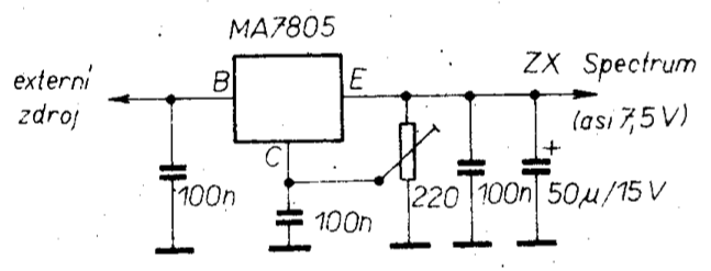
This situation can be resolved by wiring-in a voltage pre-stabiliser between the transformer and the microprocessor. For this pre-stabilisation function one can use a MA7805 monolithic circuit and connect it as per figure obr.28. This stabiliser may be attached directly to the outside of the transformer case including its heatsink and to place the remaining components inside the case. In such a way we have modified many varieties of power supplies and over the years they continue to function to the absolute delight of their users.
The output voltage of the pre-stabiliser should be adjusted to be the smallest on which the ZX Spectrum still reliably works. The lower voltage limit is ascertained by picture breakup - then one just needs to slightly increase the pre-stabiliser output voltage and you’re done. The ZX Spectrum voltage needed tends to be about 7.5 Volts.
The microcomputer then contains its own +5V voltage regulator which powers the majority of its circuitry.
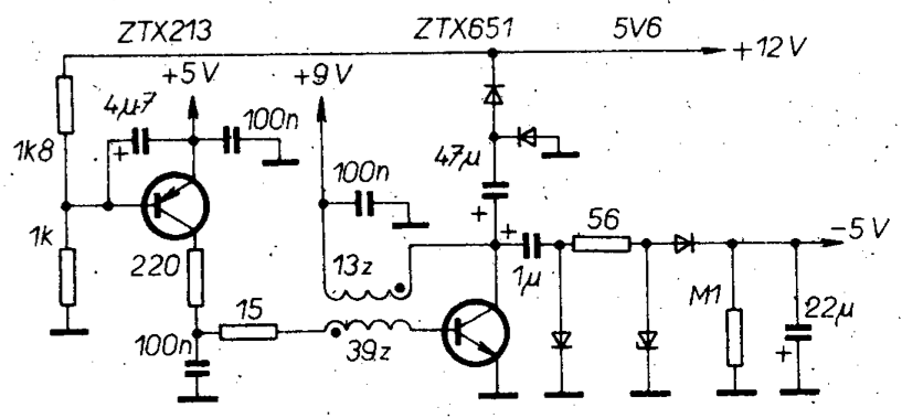
Additionally, TV RAM dynamic memories of type 4116 need +12V and -5V voltages which are derived from a voltage converter. It needs to be said that this converter [1] is the weakest link in the whole microcomputer system, especially reliability wise. What’s more, in the original Spectrum versions the designers didn’t consider the possibility of destroying all the 4116 memories should the -5V supply fail (when the negative 5 rail did drop-out, the 4116 chips were destroyed every time - guaranteed).
This short coming was partly resolved by a modification to the voltage converter, in particular to the parts that derive the +12V power. The modification consists of interrupting the feedback loop of the +12 generating circuitry, as per figure obr.29. This guarantees that the +12 volt rail will be “disconnected” when the voltage converter fails, since it works in pulse mode.
Personal Microcomputer MISTRUM
The birth of the Mistrum microcomputer was an attempt to construct a microcomputer compatible with the ZX Spectrum line. Given the limited availability of integrated circuits in this country and the complete lack of the custom ULA IC that is used in ZX Spectrum, the first version of a ZX Spectrum clone machine that was designed and assembled was a carbon copy of the Spectrum design. This version (design iteration) only used ICs that were available on the local market (in particular ICs imported to this country from the Communist Bloc such as the TTL LS range).
Additionally, the architecture chosen was the same including a shared main memory (TV RAM). It was here that the first problems cropped up, such as the selection of suitable memory chips, since for TV RAM one needs the 4116 types with an access time of at least 120 ns. As is well known, memory chips in this country are not graded by speed and thus we were left on our own. One could either choose working ICs from a very large IC pool or construct a specialised memory tester - both options are unwieldy for the average constructor.
Another problem in realising a workable microcomputer model has turned out to be the sheer number of ICs, in particular the section emulating the ULA circuit. The total number of IC packages used was about 100. Such a large number is unsustainable for the amateur constructor, not only due to the design complexity and circuit board size, but also overall reliability as well as price. For these reasons a new microcomputer variant was introduced whose primary driving goal was the minimisation of IC packages by selecting the most modern ICs that are actually available in this country.
Also taken into account was the option to make use of some important ICs which, while foreign, are generally available for purchase in this country for example through classifieds. In this way simplification was achieved along with a reduction in overall cost.
Another design criteria was the ability to use a colour or (for simpler microcomputer assembly) monochrome TV receiver with a direct video-in (having appropriately modified the receiver) or to use the Antenna input.
Microcomputer MISTRUM has thus come into being after extensive practical experience and its designers made use of all the knowledge gained during their analysis of the functioning of a real ZX Spectrum. The naming is totally innocent and is used to distinguish the new machine from scores of clones and other makes around the world.
MISTRUM Microcomputer Technical Parameters
- Microprocessor: UA880D (Z-80A)
- CPU Clock rate: 3.5 MHz
- ROM size: 16kB (8x2kB or 1x16kB EPROM)
- RAM size: 64kB
- Video output: monochrome video out; monochrome UHF out; colour video out (PAL); colour VHF out (PAL); optionally RGB out
- Compatible controllers: CURSOR, SINCLAIR 1
- Power supply: 220V/10VA; 5V/2A
- Software compatible with ZX Spectrum
- Long life keyboard
- Buffered external bus
- Separate input/output for cassette tape
- Volume control of inbuilt speaker
- EPROM can be disabled by software
- Inverse-video ability
- Ability to disallow ULA from interrupting the CPU
- Built-in RESET and NMI buttons
- Removal of hardware bug present in the genuine ULA IC
- Increased CPU throughput - speed-up of 3%
- Lesser demands on the access speed of RAM
MISTRUM Microcomputer Architecture
During the design phase, the designers made use of a method of minimising the IC package count while achieving a machine equivalent to a ZX Spectrum.
In the subsequent discussion we will use the term ULAM even though we are no longer referring to a custom IC (an Application Specific Integrated Circuit – ASIC) but rather to a part of the Mistrum microcomputer comprised of discrete circuits. This part of the Mistrum carries out the functions that the ULA performs in a ZX Spectrum even though to achieve this functionality it relies on different principles. In addition it contains additional functionality which will be described later on.
From the Spectrum microcomputer analysis it is evident that the most complex function of the ULA circuit is the shared DISPLAY FILE memory access and the resultant speed requirements imposed on this memory as well as on the ULA itself. Similarly, the large amount of video data to be processed (4 bytes per one TV RAM ULA access) complicates the design solution of an equivalent replacement circuit. Last but not least, the method of ULA and CPU synchronisation is rather complicated in the original ULA circuit. All these points were taken into account when designing the Mistrum microcomputer and the resulting ULAM circuit is fundamentally different.
A significant circuit simplification of the ULAM (by up to 30%) was achieved by giving it its own 8k static video memory. By doing this, it was possible to utilise the 4164 memory chips for the CPU memory. It also became possible to use the Mistrum with 64kB of RAM.
The architecture of the Mistrum is in figure obr.31, from which one can glean the layout of the various memories and the function of the ULAM circuit including outputs for a TV receiver.
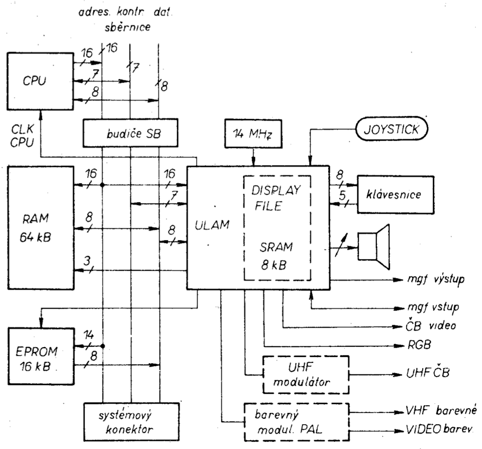
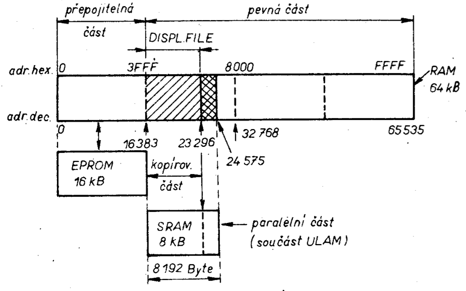
The memory map is in figure obr.32, where the placement of the 16 kB EPROM is evident. After microcomputer power-up, the EPROM is connected to the system, i.e. mapped-in, from address 0000 to 3FFFh; the remainder of the address space is occupied by RAM i.e up to the end at FFFFh.
It is possible by programmatic means to disable the EPROM memory and in its place to enable the bottom quarter of the 64kB RAM – the bottom quarter of the RAM is disabled when the EPROM is in use.
The DISPLAY FILE area is again mapped in the 64 kB RAM starting at 4000h and is 6912 bytes long, the difference being that its data is not used for creating the video output. For the video output function we utilise the 8kB SRAM into which we clone the information that the CPU is writing to the main RAM in the DISPLAY FILE address space. For this parallel “copy” function the ULAM circuits need to “catch” the DISPLAY FILE address and data that the CPU is writing. At a suitable moment, when the SRAM is not being read for video output, the previously caught DISPLAY FILE data are written to the SRAM. This copying activity is symbolically shown in figure obr.33.
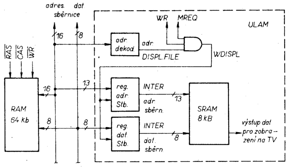
The registers used for latching the address and data values that the CPU is writing to DISPLAY FILE in the 64kB RAM are asserted by the WDISPL signal. The function of this signal can be described thus: WDISPL = MREQ . WR . ADR DISPLAY FILE. By these means one is assured that only the part of DISPLAY FILE marked by a hashed-line in figure obr.32 will be copied.
By means of suitable timing of the part of the ULAM circuit which handles the video output we have avoided the need to pause the CPU during its write to the DISPLAY FILE (no need for cycle stealing). The circuits accessing the SRAM are fast enough to perform video data reads as well as writes of the new data. Most CPU instructions that access memory always take more time to perform their action than the time it takes for a single SRAM video data fetch. A partial complication will arise only if the CPU decides to write 16 bit data to DISLAY FILE in a single instruction. In diagrams obr.8 to obr.12 we can see the types of instructions marked by a star (asterisk) which utilise two consecutive memory write cycles. For these instructions the CPU clock will be paused temporarily and this depends on the mutual timing relations between the CPU and ULAM. The details of this interplay will be described later. From the above it’s evident why the operating speed of Mistrum is faster compared to ZX Spectrum.
In the next section we will describe in detail the construction of the single board Mistrum microcomputer in its minimal configuration with monochrome TV monitor output (with one +5 V power supply). Extending the configuration by a colour modulator or by a UHF modulator depends on the requirements and abilities of the home constructor. We will also point out where the TTL LS ICs can be substituted by the plain TTL series ICs (which are more widespread in this country). The microcomputer has been designed with certain variability in mind, but having said that, in some cases that was simply not possible.
Description of the microcomputer wiring
The schematic (wiring) diagram is in figure obr. 34. The basis of Mistrum microcomputer is the classical wiring-up of the microcomputer section which consists of the microprocessor, a RESET circuit, bus transceivers/buffers and memories.
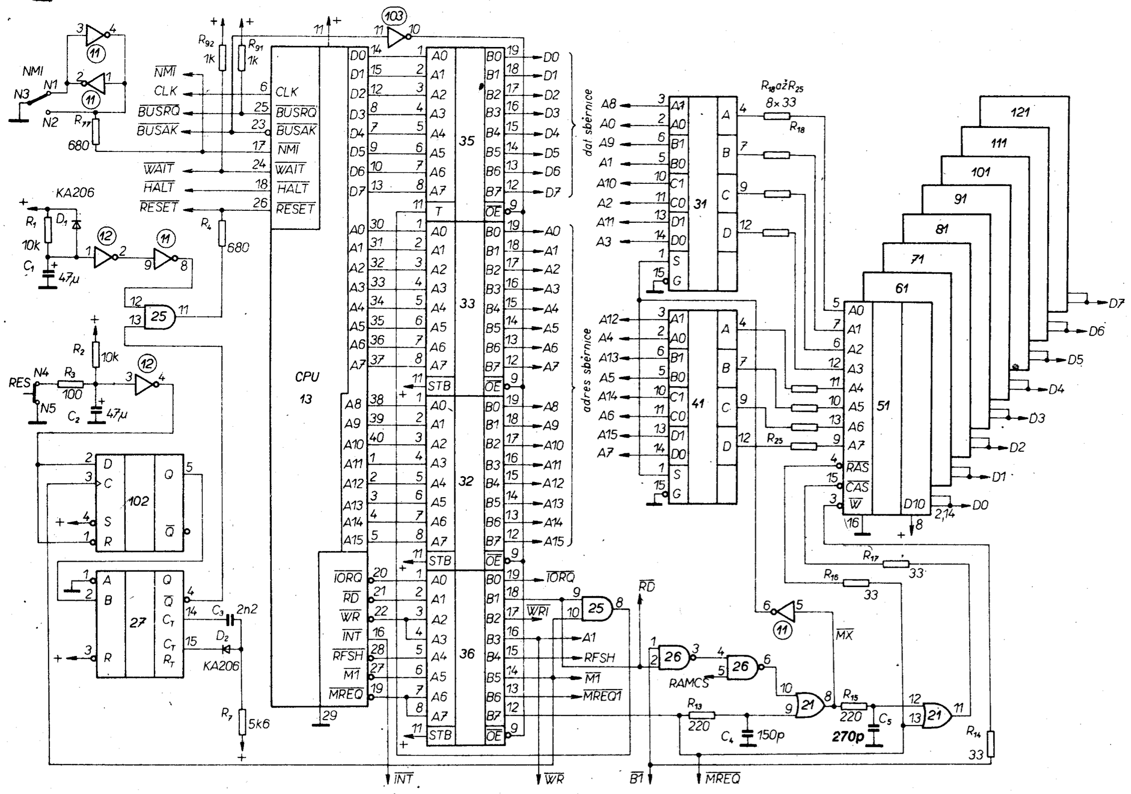
The microprocessor type is the UA880D imported from East Germany (a Z-80A equivalent). The system clock is generated by the ULAM and is 3.5 MHz. The power-on RESET circuit comprises resistor R1, capacitor C1 and diode D1. This feeds to a Schmitt (hysteresis) inverter at position 12 and is then ANDed (gate 25) with a RESET pulse from IC 27. A RESET pulse can also be generated by depressing the RES button. When this button is pressed, C2 discharges through R3 and the output of IC 102 goes High. The M1 signal from the microprocessor will clock IC102 so that the rising edge of C will cause Q (105/5) to go high. This enables the flip-flop of IC27 which actually generates the desired RESET pulse of 3.8μS duration. This length of the RESET pulse is of sufficient duration to cleanly reset the CPU without being so long as to lose data in the dynamic RAM (drop-out) due to disruption of the dynamic RAM refresh. The pulse duration is governed by C3, R7 and D2. The RESET pulse is AND gated by IC 25 pin11 and passes to the CPU via a resistor R4. This resistor separates the internal RESET from external RESET, such as from an external connector. The inner NMI line is similarly isolated by R77. To avoid race conditions of the NMI push button (button bounce) it is debounced by an RS flip-flop of IC 11/2 & 4.
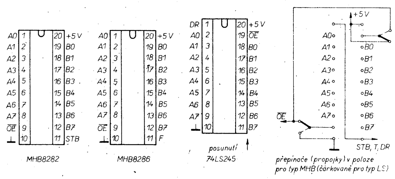
Inputs WAIT and BUSREQ are connected to a +5v supply via pull-up resistors R92 and R91 as well as being taken to a system connector. Bidirectional data signals are buffered by IC 35, type MHB8286 – this constitutes the data bus of the system, the “DATABUS”. Similarly the ADDRESS bus is also buffered as are the control signals IORQ, RD, WR, RFSH, M1 and MREQ. Because these are output signals we buffer these by MHB8282 integrated circuits at positions 32, 33 and 36. The microprocessor has been buffered this way for two reasons: because of the fan-out of its’ own system as well as to cater for connection (loading by) external peripherals and also to protect the CPU (the CPU tends to get damaged when interfaces of questionable quality are attached!).
Due to the large current draw of the buffers it is possible to replace the MHB8282 and MHB8286 by LS parts 74LS245. These components are birectional however that’s OK. The printed cuircuit board allows for this substitution. Figure obr. 36 shows the IC layout together with the needed wiring. For completeness it should be noted that the buffers are output-enabled by the BUSAK signal in its non-asserted state of H (it is possible to use DMA mode). Data buffer at 25 is controlled by circuit 35/8 depending on the direction of CPU data (from/to).
The main 64kb RAM memory consists of eight ICs in positions 51, 61, 71, 81, 91, 101, 111 and 121. The type used is the 4164 imported into this country from the USSR under the designation KR565RU5. The memory’s address lines are wired up in the traditional manner using multiplexers 31 and 41 which are 74157 types or perhaps LS257. Protective resistors R14, R16 to R25 are used to suppress current spikes during the RAM’s operation. Control signals generated for writing, reading and refresh are the RAS and CAS. The circuit that guarantees the correct timing of these signals was taken from the ZX Spectrum and modified slightly. What is interesting about this circuit is that it doesn’t at all use the special purpose CPU pin RFSH that is just for this purpose – the designers of the Z80 microprocessor might well be dismayed to learn this.
IC 26/3 AND’s signals RD and WR which, when the memory is freed by signal when power is applied to the machine, will enable the EPROM memory into the address space i.e. for the first 16kb it will be L. Thus RAM memory that would otherwise occupy this address space is disabled by the RAMCS signal. If the EPROM is programatically deselected (see further) then for the whole 64kb address space we have signal ROMCS active and RAMCS is High and thus it disables the EPROM and allows all of the 64kb RAM to be seen.
The RAS signal is generated directly from signal MREQ and it is so during both writing, reading as well as during the refresh cycle. A delay element consisting of R13 and C4 will delay MREQ signal and should the memory be enabled (banked into the address space) by the RAMCS signal then an MX signal at 21/8 is generated from signals RD or WR, as per figure obr. 37.
After the address multiplexers 31 and 41 get switched over by signal MX, the suitably delayed (by R15 and C5) signal CAS will be generated. From the interconnections it is evident that when the refresh cycle is active and if at the same time the RAMCS memory blocking (disabling) signal is also active then the ANDing at 21/10 is blocked and thus the MX and CAS signals do not get generated. In that case the only signal generated is RAS and it is only used to refresh the 64kb RAM contents. The MREQ signal is connected to a system connctor pin and it is also duplicated (buffered by 36) as MREQ1. The purpose of MREQ1 is to allow DMA access.
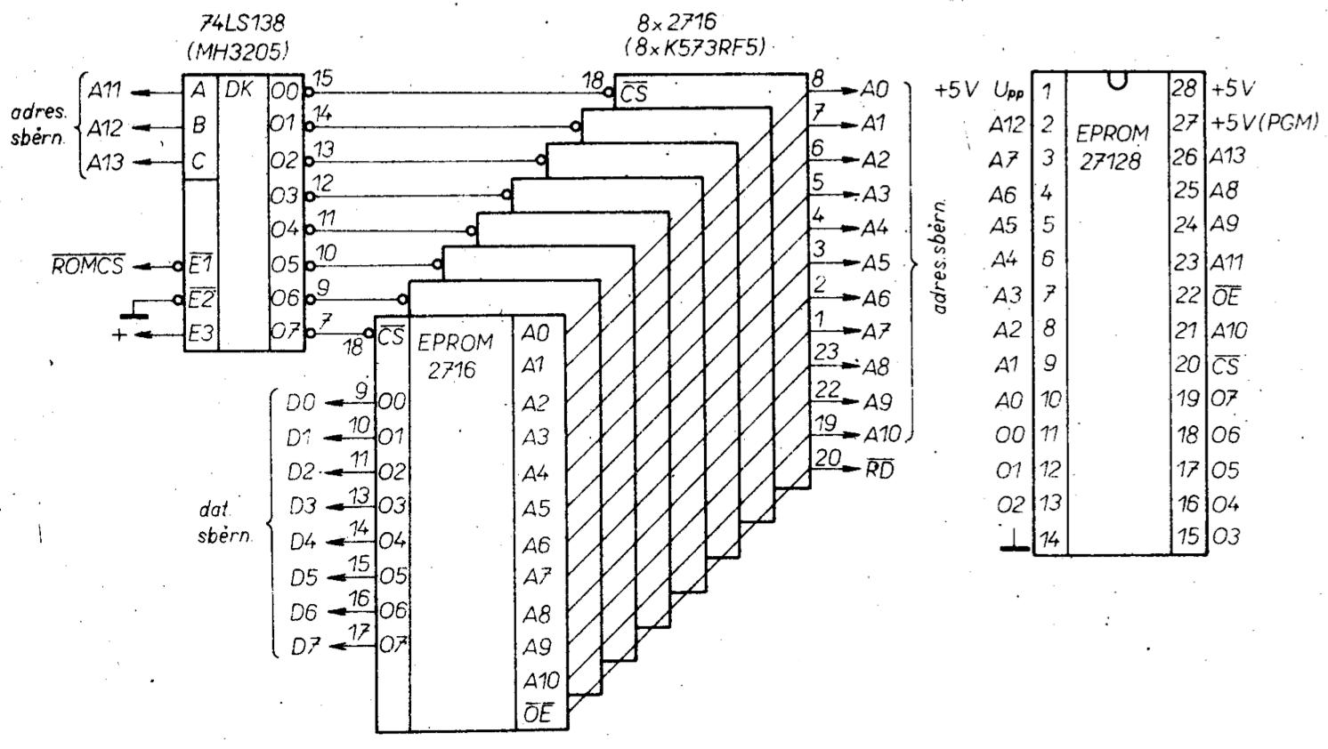
The operating system including the BASIC interpreter is stored in the EPROM memory which is mapped to the first 16kb of the total 64kb address space. The software for MISTRUM will be discussed in a dedicated edition. The EPROM memory used is the 27128 / 250ns. Sometimes it is possible to obtain these chips via A.R. magazine classifieds or similar means, otherwise they may be substituted by type K573RF2 or K573RF5 memories imported from the USSR. These memories have 2kb capacity. Figure obr.38 shows the connections. The physical arrangement may involve using an extra PCboard which would contain all the needed memory chips including the address decoder ICs. Because we have used bus buffers on the motherboard there is no need to use bus buffers on this EPROM PCB with 2716 chips. Figure obr.39 shows this additional EPROM PCB board. For the board pins (to slide into the motherboard) we used the pins from type FRB connectors which in practice have proven reliable. Similar arrangements can be devised for other memory types. The motherboard EPROM socket was deliberately designed for the 27128 type not just due to size constraints but also because there are too many possible variations with many differing types of EPROMs.
Description of the ULAM circuitry
The ULAM circuits make up an independent part of the Mistrum microcomputer and they replace the custom ULA ASIC that is used in the ZX Spectrum. The ULAM circuits make use of a different way of acquiring data for display on a TV screen. By doing it this way, we were able to reduce the requirements for the number of inner registers (ULA FIFO) as well as simplify the ULAM timing circuitry (partly thanks to the use of static VIDEORAM).
The speed requirements placed on the VIDEORAM (SRAM) are only 280ns, which makes them only half as demanding as that of the ZX Spectrum.
In figure obr. 40 is the ULAM block diagram. The core circuit consists of the time-base and address generation for the SRAM. This circuitry generates all the timing signals that control the whole ULAM. Lower SRAM addresses are buffered into an internal address bus of the SRAM. The higher part of the address is routed through transformation block F, which co-ordinates the addresses for attributes or data. As well as that, onto the internal address bus we also route the address from the copy registers during CPU writes to DISPLAY FILE. This internal address bus is tri-state. As well, the time-base generates all timing pulses needed for a TV receiver (RSI – row sync. pulse, RZI – row blanking pulse, BURST – colour carrier sync. pulse, SSYN – frame sync. pulse, SSI/2 - SSYN divided by 2) and also signals “blok” and INT.

The SRAM uses the internal data bus through which the previously latched data is writen to this RAM. This previously latched data is the data which the CPU is writing to (or was writing to) the DISPLAY FILE 64kb RAM.
The content of the SRAM is transfered over the internal data bus to a temporary register (during attribute processing) or into a parallel-to-serial converter during data processing. From this temporary register the attribute is written into into the main attribute register at the moment of its’ use (when it’s being displayed).
The output multiplexer VMX is switched over to BORDER mode or attribute mode by signals “block” or “zobr” in a manner similar to that shown in figure obr.20.
The PAPER and INK attributes are, during their videodisplay, serially shifted out and perhaps inverted (when FLASH = H). The VMX output represents the three bit RGB colour information in TTL levels. The brightness component consists of the Y output as per the BRIGHT attribute. These four bits together with synchronisation pulses are fed to the D/A inputs and this DAC functions as a videomodulator for a B&W TV monitor. The block “copy logic” together with timing circuits ensures that the CPU and ULAM are synchronised (arbitrated) – including the writing into copy registers by the STB signal.
To service the keyboard and to read data from the cassette player, the block INKEY is used, which is addressed as an input port with an address of 254. In a similar manner, the BORDER and BEEP register/s as well as the output to the cassette player, function as an output port sharing the same address. To decode the DISPLAY FILE address space we use AD1 address decoder, which ensures that the data copied is only from the designated address space and thus it doesn’t slow down the CPU when the CPU is working with variables which are also located in the TV RAM area. Compared to ZX Spectrum’s ULA circuit, our ULAM contains an additional block. It is block AD2 which by means of 64 kb address decoder (signal RAMCS) together with 64kb RAM control register provides for the switching between the RAM and EPROM memories. In actual fact, blocks AD1 and AD2 make up a single integrated circuit because to physically realise this logic we used the one and the same PROM.
The complete block diagram should be understood as being an independent unit which, through the system bus, is connected to the rest of the microcomputer.
This unit could be used to replace the custom ULA ASIC in a ZX Spectrum, should the original ULA become faulty, however this is only the case if one is interested in monochrome output. To get colour output one would need to additionally add the colour videomodulator.
In figure obr.41 we can see the connections of the ULAM timebase and the internal SRAM circuits. The base clock is generated by an astable multivibrator (comprising inverters 122/2 and 4 of type 74S04). The Schottky version was chosen to ensure a reliable start-up and reliable running, because with other types of multivibrators there were dropouts. These dropouts didn’t seem to affect the normal function of the microcomputer (and besided they were very difficult to measure). The dropouts were only discovered during the development of the colour modulator when we found picture interference.

The frequency is governed by a 14 MHZ crystal. The crystal stability is not critical; when the frequency is lower the picture will be a little enlarged; for higher frequency the picture will be smaller instead. The only aspect that is critical is for the TV receiver to keep picture synchronisation (lock) as well as the frequencies generated by programatic means such as the frequencies during SAVE, BEEP). In practice we had success even with a 13.6 MHz crystal without problems.
The ULAM timing circuit starts with a synchronous divider at 53. By dividing this 14MHz base frequency we get the required clock signals for timing the activity of videoinformation reads and writes from/to the SRAM memory (DISPLAY FILE).

In figure obr.42 we see the timing diagram of the most important timings. To guide the reader we shall firstly explain the individual timing signals:
7M – is used to (re)?write output videodata and synchronisation pulses at the output register 114 to remove collision states.
3M5 – is used for CPU clock and for the LOAD signal.
F1 – is used for ULAM timing when the ULAM is working with attributes or data.
F2 – This signal defines the writing/reading of videodata to/from SRAM. It also generates OEU which is used to output the address part of ULAM during videodata output and also to rewrite the attributes from temporary registers 84 and 85. F2 together with F1 generate signal D/A (DATA / ATTRIBUTES) used to switch the attribute address during reads from SRAM, during cycle C4.
D/A – is used for writing attribute data into temporary registers 84 and 85.
LOAD – this signal defines the time interval used for parallel write of data from the SRAM into the parallel-serial converters 74 and 75.
From the timing diagram in figure obr.42 one can see the division of the base clock into four cycles C1 to C4. Cycles C3 and C4 are reserved for reading attribute and data from SRAM which will be displayed in subsequent cycles C1 to C4 in synchrony with the falling edge of 7M.
When the CPU writes data into the DISPLAY FILE address space in the 64kb RAM, the address of the written byte will be routed to registers 43 and 46 and this byte will be simultaneously written using the STB signal into register 45 (strobed into 45 by STB).
Copying of the byte into SRAM memory is dependant on the timings of CPU and ULAM (the CPU works independently of the ULAM timing but synchronously with the 3M5 clock).
If the write occured during cycle C1 then simultaneously a (single) byte will be written into SRAM during C1 and C2. In this case signal W will be active which output-enables the latching registers and at the same time this signal will be the write pulse for SRAM. However, should a write into the latches occur during cycles C2, C3 or C4 then the data transcription into SRAM will take place in the subsequent cycle C1, C2. During single byte CPU write instructions the process of transcription into SRAM is uninterrupted and thus there is no need to pause the CPU clock (to cycle steal). A different situation arises however when 16 bit data is written into memory, when the CPU causes two consecutive memory write cycles. This will create two consecutive requests (RQ) for transcription and were the CPU clock not paused, then either the second byte would be lost or there would be a “drop-out” in the picture displayed on the TV screen. The matter of pausing the CPU clock will be elucidated later.
Through the action of outputting videodata during cycles C3 and C4 signal OEU is generated (figure obr. 42) which output-enables buffer 63 and multiplexers 64 and 65. In this way the address of the current attribute is applied to the SRAM memory which, in the next C1 to C4 cycles, will be used. The D/A signal during C3 is in state H and thus the multiplexers 64 and 65 are switched to generate attribute address. (This activity is similar to that shown in figure obr.16, however it proceeds in reverse). Outputting attributes prior to data was chosen to make things simpler. After 280ns passes (C4), signal D/A is generated which, on the rising clock edge, will transcribe the attribute from SRAM into a latching register (84 and 85).
At the same time an inverted signal, D/A, is generated which will switch multiplexers 64 & 65 to connect data address. In this way, during cycle C4, the data in SRAM is read out. During the change from cycle C4 to cycle C1 the LOAD pulse is generated which enables the writing of parallel data output-enabled from the SRAM. On the falling edge of 7M the data is written into a parallel-to-serial converter 74 & 75 and immediately used for TV picture generation. During this time the accompanying attribute in the latching register is transcribed into attribute register during the rising edge of OEU.
Addresses of data destined to be displayed are supplied by synchronous dividers 54, 55, 56 and 57 of type 74LS193. Because these data addresses have a fixed place on the TV screen (figure obr.14) they are in synchrony with row and frame synchonisation pulses. For these reasons, the counters shorten these cycles so that we can make the most use of these counter signals (counter signals for addressing SRAM as well as for TV receiver synchronisation).
In figure obr.43 we can see the detailed generation of address and TV receiver synchronisation. Pre-setting?reload impulse ZKR1 sets signal E into state H. Other outputs at 54/3, 2 and 6 are fed back to their pre-set inputs and their state will not change when ZKR1 pulse arrives. Signal “zobr” is the same name signal as in figure obr.20 and it delineates the information zone on the TV screen from the colour border (BORDER).

Shortening pulse ZKR1 will shorten the binary counter cycle from 32 to 28 (it is necessary to achieve the time of 64μs per one TV row (TV line)). The PROM 113 (type MH74188) plays a part in this shortening process by storing all the states needed for the creation of row synchronisation impulses, figure obr.45. In figure obr.44 we see the schematic diagram for attribute processing as well as generating row synchronisation impulses. At address 19 the PROM 113/1 will output H for the following ZKR1 pulse logic. When strobed by timebase B we trigger a monostable circuit comprising gate 112/8 and inverter 12/12 together with discretes C9 & R50. This (ZKR1) pulse will pre-set (load) counter 54 and together with counter 55 - address B to “zobr” - will cause a jump to address 23 in the PROM 113. This action signifies the start of a new TV line (TV row) and generates the row synchronisation lot (RZI, RSI and BURST). This situation together with the layout of the displayed information is shown in figure obr.43.


Addresses marked B, C, D to M are equivalent to the ones marked A0 to A11 in figure obr.16 with the provision that they are not written into memory twice (as is the case for dynamic rams) but rather are written only once (in one go). To achieve this we make use of tri-state circuits 63 (MHB8286) and 64,65 (74LS257). Multiplexers are simultaneously used to adjust the attribute address into a data address.
For the copy registers we used circuits 43, 46 and 45 of type MHB8282. These IC’s do have a high current supply (fanout?) capability but unfortunately are neither made in this country nor imported, that is no similar tri-state latches are imported. The writing into the copy registers is strobed by the STB signal which is generated simultaneously with signal WR during the CPU’s write into the DISPLAY FILE. The latched address and data in the copy registers is output enabled by signal W and this signal will simultaneously write the data into the SRAM memory at the appropriate address.
The SRAM consists of four CMOS 6516 IC packages. The manufacture of these memories in this country is schedulled to begin soon. The architecture is 2048 x 8 bits and the access time fully satisfies the required 280ns. Because for DISPLAY FILE we need a size of 6912 bytes we have used for the SRAM four 6516s. For the address decoder the 74LS138 is used or MH3205 may be substituted. Because it is possible to obtain the 8kb 6564 memory by means of classifieds or import, we have designed the PCB to also allow for the use of a single 6564 memory chip. To take advantage of this possibility the conctructor needs to use wire links on the PCB and also to leave out circuit 66 (the 74LS138). If wanting to use other memory types, one just needs to keep in mind the 280ns access time requirement, otherwise the SRAM choice is not critical.
The IC package pinouts for 6516s and 6564s are in figure obr.46. From the SRAM, the data is written into a parallel-to-serial converter (74 & 75) consisting of D195 shift registers made in East Germany. While this type of circuit is somewhat less well known among hobbyists, it is however the best choice in this application. The now serial data are clocked out of the converter by the 7M clock and routed to circuits 72/11, 8. These EX-OR gates function as an inverter with a control-input??. The serial data stream is inverted by signal FL3 which is active in instances where attribute FLASH = 1. In that case the FL3 signal with a frequency of 3Hz will toggle the serial data stream so that the INK and PAPER attributes are continuously swapped over. On the screen this effect manifests itself as a blinking of the displayed character.
The ULAM designers when designing the ULAM took into account several practical additions/features which are often sought in a ZX Spectrum. One of these is Inverse Video. Such a modification has been documented several times in various magazines, foreign and domestic, and in our ULAM design we have provided this feature almost for “free”. Inverse Video is due to the modulo2 ORing function of the EX-OR gate at 72/8. To select Inverse Video one needs to to manually flip a DIL switch on the PCB. Those users who wish to use this function frequently should extend the (DIL) switch to the outside cover of the microcomputer.
At position 84 and 85 we have circuits (attribute temporary registers) which retrieve from the SRAM an attribute which will be used in subsequent cycles C1 to C4. From these registers the attribute (which is strobed by the OEU signal) is written into the main attribute registers at position 94 & 95. These registers are made up of four D-type flip-flops, 74LS175.
Figure obr.41 shows the CPU clock circuits. Gate 62/3 allows for pausing the clock in instances of 16-bit writes into the DISPLAY FILE by signal STOP. Inverter 122/8 together with transistor T5 ensure a higher level of the logic 1 level and make for a sharper edge of the CPU clock. This part of the circuit containing the transistor is not neccessary and an impoverished hobbyist may leave it out and replace it with a 330Ω resistor connected between the 122/8 inverter output and +5v supply. This beefed-up circuit was included in the system to make for a quality clocking signal when it is loaded-down by the connection of external peripherals (eg. SIO). Figure obr.44 shows the connections of the output multiplexer VMX, one which switches over attributes and BORDER.
This multiplexer consists of two circuits 104 & 105 of type 74LS253 or perhaps MH74153. To switch the border of the TV picture we use the MUX signal which is generated by the ORing of signal “zobr” (defining-in the horizontal direction) and signal “block” ? (defining-in the vertical direction) at gate output 21/3. The flip-flop at 47/9 only shifts such generated signal by the (?width of the?) B clock compared to the total time delay of the videodata displayed on the TV receiver. When the MUX goes H the multiplexer will send through 3-bit border colour data. When MUXXL the multiplexer will switch the INK and BORDER attributes depending on the serial bitstream from the SRAM selected by the SERIAL DATA signal.
The multiplexer outputs at 104/7, 9 and 105/7 carry the 3-bit colour information of the currently displayed dot on the TV receiver. These bits are delayed by circuit 114 to avoid glitches during the switching of the multiplexers. These glitches can be seen on a real ZX Spectrum as translucent edges at the 8x8 raster especially when the character is set to blink. For completeness it should be noted that even a 10ns impulse is enough to cause picture infidelity.
VMX output 105/9 carries the BRIGHT attribute to increase the brightness of the displayed point. It is processed in the same manner as for the INK and PAPER attributes (except for black for which it is suppressed). Multiplexer inputs 105/12 & 13 are connected as a “fourth” bit of BORDER to signal BOOT. As was stated earlier, it is possible through programatic means, to disconnect (disable) the EPROM and in its place enable the first quarted of the 64kb RAM. This disabling is achieved when signal BOOT = H.
To make better use of multiplexer 105 the BOOT signal is wired-up as the BRIGHT function, although it increases the brightness of the BORDER! This is another point of difference compared to the Spectrum and is used only for a visual confirmation of the BOOT state (mode EPROM/RAM 64kb) on the TV screen. Should one not like this feature it is possible to remove it by breaking the PCB trace between the BOOT signal and 105/13 and instead connect together all four inputs 105/10, 11, 12 & 13. (Crafty programers can surely and easily make use of this function).
We talked already about the generation of row synchronisation pulses in association with the shortening of the address counter pulses by the ZKR1 signal. For completeness let’s add that the placement and duration (width) of these pulses is defined in the PROM memory 113 of type MH74188 and thus it is conceivably possible to change their placement and width in steps of 2.2μS (the timebase B period) should the attached TV receiver have a bad synchronisation. Of course by shifting the sync. pulses the whole TV picture will shift as well at the expense of the left side (BORDER, LB) figure obr.43.
The sync. pulses RZI and RSI are again transcribed by circuit 114 clocked by 7M and this is to avoid a hazzard state (glitch) in the PROM memory. This hazzard state caused by counter time delays during the cycle shortening was causing picture glitches which appeared as a continuous line one characted away from the videodata field.
Counter 67 is clocked by the CA signal that is arriving from the outputs at 57/12 in figure obr.41. The outputs of 67/7 generate signal 3H which determines the character flashing speed during the FLASH function.
The flip-flop 47/5 in figure obr.44 is used to generate the “blok” signal which defines the vertical field size of the displayed information. Its generation is obvious from figure obr.45: at the high-going clock-edge of signal M during N it is set to logic 1. On a subsequent high-going clock-edge of M during N it becomes logic 0 and thus signal “blok” terminates. (Translator’s note: the description doesn’t quite seem to match the timing diagram as I see it – the last line should read: “during NXL”).
At the same time monostable 47 and inverter 12/8 and discretes C13 & R64 will generate shortening impulse ZKR2. This ZKR2 pulse will shorten the cycle of counters 56 and 57 to achieve a frequency of 50Hz for frame synchronisation impulse SSYN.
The circuitry to generate SSYN and INT is shown in figure obr.48. Flip-flop 15/9 is reset by monostable 12/10, 72/3 with discretes C14 & R65 on the falling edge of N as per figure obr.47. Signal SSYN is terminated by the rising edge of I. SSYN governs the frame syncing of the TV picture. The falling edge of SSYN triggers multivibrator MKO 27 of type 74123, which generates interrupt INT for the CPU. The length of this INT signal is about 9μs. The input B of 27 is connected to +5V through resistor R66. The B input is also connected to a DIL switch which allows the user to disallow the ULAM from interrupting the CPU. This feature can be used for example to speed-up calculations in instances when there is not any need for access to the keyboard and if the CPU doesn’t have this feature available programaticaly. Resistor R66 allows for externally blocking INT over the system connector by connecting to +5V.
? obr 46 ?


Figure obr.49 shows the IC circuits which control the writing into the copy registers, transcription into SRAM and CPU clocking.

The key component is the address decoder 52 which is implemented as a MH47S571 memory element. This memory monitors the DISPLAY FILE over a range of addresses from 4000H to 5BFFH. Given the small number of address input pins and to achieve the greatest simplification we have for addressing only used lines A8 to A15. This defines the address space in the area of DISPLAY FILE which can be monitored. Figure obr.50 lists the contents of PROM 52. The first half of the memory covers the address space (in 256 byte pages) of the 64kb when BOOT = L. The PROM’s Y1 output (52/12) will go low (0) when the address is in the range 4000H to 5BFFH ie. decimal 16384 to 23551. This part of the DISPLAY FILE is shared with the PRINTER BUFFER area.

From the above one can see that the ULAM actually also copies the area used by a printer. This shortcomming however is not a problem since a printer is used infrequently and what’s more, when it is in use, it doesn’t make use of 16-bit memory access operations. The 5C00H area (decimal 23552) is the system variable area and these do get addressed and thus do not get transcribed into SRAM! In a similar way we have programmed the output at 52/10 except that compared to Y1 it is inverted (savings of one inverter). At the memory’s pin 52/11 is the Y2 output which becomes the ROMCS signal to enable EPROM (active low) and it also becomes the RAMCS signal which blocks (disables) the first quarter of the 64kb RAM.
The second half of the PROM 52 (while BOOT = H) works with the DISPLAY FILE area in a similar manner except that signal RAMCS is enabled for the whole address space by logic H (and thus ROMCS disables the EPROM). In this area the fourth output 52/9 (Y4) becomes active and becomes logic H for the area of the first 16kb. Its purpose is to disable any attempted writes into the 64kb RAM (in this lower 16kb area of this 64kb RAM) so that the RAM can be used in place of the EPROM. The reason for wanting to do this are obvious.
(Translator’s note: You would want to do this in the absence of the EPROM not only saving on IC packages but also if you are simply unable to find such an EPROM for purchase! In that case you would load the ZX Spectrum Operating System/BASIC interpreter from cassette tape into this lower 16kb RAM when writes to it are enabled and after that, disable the writes. Then you would use your MISTRUM as if ZX Spectrum. You could also load custom BASICs/OSes such as Czech or Slovak ones with CZ or SK character sets etc. Or perhaps a different programming language such as FORTH, Pascal etc., instead of BASIC.
On a second note, I suppose you’d need at least SOME eprom to allow this loading (as in a BOOTLOADER), so an impoverished communist country hobbyist might have used the more widely available 2716 EPROM (its Russian equivalent) for the small bootloader code which would then load the main BASIC etc. from tape. In the year 2016 one might have a large 8kb or 16kb EPROM/EEPROM/Flash memory or Non Volatile RAM such as MRAM or FRAM and these could contain various programming languages or operating systems in the various areas (BANKS) of such a large ROM chip. The ROM/NV RAM would then be wired up (and with a switch for the user) such that the user could switch between the various ROM BANKS prior to reseting the machine.)
Using the PROM memory as an address decoder was done on purpose. A more advanced constructor will no doubt have realised that this way it is possible to map the DISPLAY FILE at the end of the address space in the second half of PROM and by this to allow for the implementation of the CP/M operating system on the MISTRUM. This “CP/M” mode can be switched in and out under program control and thus there are no barriers to running CP/M on the MISTRUM. The output enable at 52/13 is fed the MREQ1 signal and is also connected via a 10k resistor to +5V supply. The purpose of this resistor is to guarantee logic H when the buffers are disabled during DMA transfers.
In this mode PROM 52 is not enabled and signal RAMCS is thus H. For the same reasons the signal WRI is wired up the same way using resistor R31.
When the CPU writes into the DISPLAY FILE area the PROM 52 generates logic L on its Y1 output (and logic H on output Y3) for both logic levels of the BOOT signal. Because this constitutes a memory write cycle the signal MREQ is active low and so is signal WRI. The [request for write (RQ) to SRAM] flip-flop 73/9 is cleanly pre-set to logic H (negative logic) by its’ preset input 73/10. When the CPU finishes writing a byte into the 64kb RAM the signal WRI will set 73/9 to L and this prevents a subsequent second memory write (16-bit write) that could otherwise occur (it blocks the generation of STB signal at 112/5 and releases 73/4 for a potential pausing at the CPU clock should a second write impulse WRI arrive – when the first write into SRAM hasn’t completed yet). Simultaneously with the first write into 64kb RAM a level H is generated at gate 112/2 (the DISPLAY FILE area) and an inverted signal WRI will, from 103/2 and 112/3, generate a copying signal STB for the address and data copy registers. After the write is complete the 73/8 will be H and will allow (if OEU = H) the generation of transcribing impulse W into SRAM. As the transcribing impulse is ending a set pulse is generated at gate 12/6 (with discretes C6 & R32) and this set pulse will turn 73/9 to logic H (a state of “request for transcription/write to SRAM satisfied/granted”).
Should the CPU however be trying to write 16-bit data to the 64 kb RAM then during this second write gate 83/6 will be logic L and this L will propagate through flip flop 73/5 (the Set input is made inactive by 73/8 because the previous transcription into SRAM did not complete yet). Circuit 73/5 will be L and thus generate signal STOP which will ensure that the CPU clock stays H for as long as needed to complete the transcription of the first byte into SRAM as well as the writing and transcription of the second byte into SRAM. The gate 83/6 switches at the exact time when the write into the 64kb ram occurs.
At this point it needs to be mentioned that the CPU memory write cycles occur “non-synchronously” with cycles C1 to C4 in the sense that the CPU signal WR may occur at any time with respect to cycles C1 to C4. This is because the CPU is carrying out a sequence of various length instructions and thus the WR impulse slides along. Should the CPU write pulse WR occur during time C1 then this will be a special case during which the signal will be subsequently written into the SRAM memory during cycle C2, figure obr.51. In all other cases (WR arriving during C2, C3 or C4) the videodata is read out of the SRAM first (C3, C4) and the transcription into SRAM will occur in the next C1 cycle. (The OEU signal at the gate output 83/9 determines the possibility of transcription to SRAM in cycles C1 or C2).
(Translators’ note: I see a small mistake. In the diagram obr.49 gate 83 has two pins labeled ‘9’ - the input of OEU and the output going to W as well as 12/5.)

From the above it is obvious why the operating speed of Mistrum is on the whole somewhat faster than that of a ZX Spectrum. The criteria for a slow down in CPU throughput is the number of 16-bit operations encountered.
From the ULAM function description it is evident that with this engineering solution we do not get collisions in instances where the I register is set incorrectly (disbelievers should try out the testing program given with the ULA description in the first part of this magazine article). The setting of this register is totally at the discretion of the programmer. Similarly, collisions during INKEY$ tests do not occur because from the ULAM principles it follows that the data bus is used by the ULAM circuit only during the writes of data into copy registers and during this the CPU conducts a memory write cycle. The ULAM doesn’t need the bus during the INKEY$ tests because it is displaying its own data from SRAM.
ULAM port functions
In figure obr.52 we can see input/output port wiring which services the cassette tape input/output, the audio converter and the BORDER colour control. The ports are jointly addressed by an active address signal, A0 = L. During addressing, there is an implicit assumption that the other address lines, A1 to A7, will be at logic H (linear addressing). A 3-to-8 decoder IC 115 serves at the port address decoder (type 74LS138 or perhaps MH3205). For circuit simplification this decoder is wired up in a rather non-standard way so that it can function for both input and output instructions. When an output instruction is being processed, signals RD = H, WRI = L, A7 = H, IORQ = L, M1 = H and address line A0 = L during addressing of 254 which is the ULAM address. Signal OUTU becomes active at 115/10 which then carries out the write into the ULAM’s output ports.

A similar situation arises during the read of 254 when RD = L (active) and WRI = H. Then signal INU gets generated at output 115/9. The address decoder is also used for switching in/out of memory. For this purpose the A7 line is used which in the ZX Spectrum is for general use. That is why this line was chosen for memory switching along with A0. A collision with the ULAM ports cannot happen because ULAM has its own address decoder. Signals OUTPORT or perhaps INPORT are active during the processing of an output or perhaps input instruction with an address of 126 (7EH), ie. during A0 = A7 = L, A1 to A6 = H.
The function of ULAM’s output port serves the BORDER register which consists of flip-flop 93 of type 74175. The inputs of this register are directly connected to the system data bus; together with BORDER bits (D0, D1, D2) the same method is used to process the information bit D3; D3 is designated for output to cassette tape. The 3-bit BORDER colour information is routed to the output multiplexer VMX; the output bit D3 is, after adjustment/shaping by discretes C8, R36 & R37, routed to the exterior connector for cassette tape use. The output voltage was set such that it is approximately similar as in the ZX Spectrum. This level can be adjusted by each individual constructor if required.
Likewise the output to the audio converter (BEEP) is selected in the same manner; when bit D4 is writen into flip-flop 102/9, strobed by OUTU, during the processing of an output instruction with address 254. The output is isolated by diode D21 (with R39 this creates a wired-OR). To this junction we route the signal from the cassette tape input amplifier via diodes D21 & D20 (a cassette tape playback accoustic verification of correct function (listening-in on the signal) – similar function as in the ZX Spectrum).
Two diodes are connected back-to-back to lower the volume of tape verification sounds compared to BEEP. (Should an enterprising constructor try to improve this listenning-in during SAVE by connecting a diode between 93/14 and the R39 resistor be warned, that the speaker will often be blocked due to poor programmatic handling of the D3 bit at the output of 93/14 !) From the wired-OR junction the signal is routed to transistor T1 which aplifies it and drives the speaker. For volume control a 220 Ohm trimmer is used and the speaker was type ARZ 087.
It is also possible to use a potentiometer for volume control and perhaps even with an ON/OFF switch built-in and install this on the outer case of the microcomputer. The type of speaker is not critical; if need be even an earpiece from a telephone handset can be used.
For inputting the cassette tape deck signal into the computer we made use of an input amplifier (increased sensitivity compared to ZX Spectrum; with a ZX Spectrum the tape deck output signal often had to be beefed up by the tape deck power amplifier and this arrangement is not always the best). The amp sensitivity is about Umv X 200mV and thus is fully adequate in most situations. What’s more, the computer amp input is over-voltage protected so that it can be used with the deck power amp output. In any case each hobbyist will choose their own way of connecting it together depending on the characteristics of their particular cassette tape deck.
The signal from the T2 based amplifier stage is converted to TTL levels and by the tri-statebuffer 17/11 is connected to D6 line of the data bus when signal INU is asserted.
Signal OUTPORT is used as a write strobe (pulse) for the 7474 flip-flop 15/5. This sequential circuit generates signal BOOT which is used to switch between the EPROM and the 1st quarter of 64kb RAM. The state of this flip-flop is governed by bit D7 of the data bus; to make BOOT = H one can use BASIC instruction OUT 126,128 or perhaps assembly code:
LD A,80H
OUT 7EH,A
In a similar manner it is possible to re-connect the EPROM memory into the address space by setting bit D7 = L to address 126 (e.g. OUT 126,0).
The flip-flop has an independent reset input at 15/1 and this is activated upon power-up of the computer. The reseting (BOOT = L) is performed by discrete components C7 and R34. This guarantees that the EPROM memory will be banked into the address space upon computer start and thus the execution of the OS/BASIC code (there isn’t any valid code in the 64kb RAM after power-up!). Thus the reseting of this circuit is not dependant on Reset button press and this was intentional. Using the DIL switch it is possible to be continuously reseting the circuit 15/5 and thus prevent the BOOT signal from changing (useful during “resurrection” attempts on a program that has gone haywire).
Diode LED1 together with R35 are only used to indicate “ROM disabled” for those constructors who disabled the increased BORDER brightness function at VMX (see previous text).
Figure obr.53 shows the wiring which allows the suppression of CPU writes to the first quarter of 64kb RAM. This technical solution is rather “ugly” in the eyes of an expert but it was fashioned towards the end of the design phase utilising the otherwise unused ULAM circuit parts. Despite this we feel confident that this otherwise very useful function will find use since of the ZX Spectrum it is often realised with great difficulty as a complex modification. By blocking/suppressing the 64kb RAM writes one can use and tweak any software without worrying that it might get overwritten/corrupted should the software ‘crash’. Let us elaborate on this issue.

As per figure obr.53 the WR signal is suppressed by an R-S flip-flop, which consists of gates 26/8 & 25/3 and inverter 103/6. When BOOT = L the EPROM isn’t disconnected. The output 25/3 is also logic L which disables 112/13. Thus the input of OR gate 21/5 is LOW which allows the output 21/6 to track its input 21/4 which is the WR signal for the whole address space except for the first quarter of the 64kb RAM, because signal RAMCS = L as per figure obr.50 (thus the 64kb RAM is not fully addressed by signal CAS). If during this time signal INPORT gets asserted the R-S flip-flop will not flip because it’s “held” by signal BOOT = L. Only LED1 will blink (but only very briefly; to make it visible it thus needs to be repeated – repeatedly blinked for example by looping the program code). Only after setting signal BOOT = H by program means (see earlier text) is it possible, by an input instruction with an address of 126 such as LET A=IN 126, to flip the R-S circuit into write block state i.e. 25/3 = H, 26/8 = L.
This will assert 112/13 so that the AND gate’s other input at 112/12 (which is connected to BLW - active High ??!!?? from PROM 52/9 (Y4)) can feed through to the AND gate output 112/11.
From figure obr.50 it is evident that only the first quarter of the 64kb RAM will be blocked. Earlier we mentioned that it is possible to implement the CP/M operating system. When moving the DISPLAY FILE by means of the PROM 52 it is of course possible to also move (re-map) the part of the 64kb RAM which we wish to write-protect.
The last input port of MISTRUM is the keyboard. It again is read by an input instruction with an address of 254 using signal INU which is buffered by 17/6 (for greater loading ability) as per figure obr. 52. [[translator’s note: should the 17/6 be 15/6 – check]]. The keyboard consists of a switch matrix with an 8x5 raster of conductors and it is attached by a connector (or perhaps permanently soldered) to buffers KL1 to KL8 which are interfaced to the address bus A8 to A15 via diodes D3 to D10 as per figure obr.54. The state of a depressed button is detected by circuits 17 and 16/2 which are tri-state. Their inputs are pulled high by resistors R8 to R12 of 4.7K Ω to define logic 1. The switch matrix is of course connected up the same as in a ZX Spectrum, see figure obr.24.
Figure obr.55 shows an additional circuit which is used only with the colour modulator. The circuit is trivial; it only divides by two the row (line) synchronisation impulse (RSI) frequency (inverter 11/10 and flip-flop 82/6 wired up to divide by two).


Video Modulator
Figure obr.56 is the videomodulator connection which mixes synchronisation impulses and converts the digital colour information (RGB) into analogue form. The videomodulator is intended to be used only when a monochrome TV receiver is modified to be a computer monitor [6]. This videomodulator was used together with a modified TV receiver (of TV brand Merkur) which are normally supplied with the SAP-1 systems and it performed to absolute satisfaction, especially considering the “clarity” of a totally interferance-free picture as well as great sharpness/crispiness (the picture fidelity is so high it cannot be compared to that of a ZX Spectrum!).

The D/A conversion of the 3-bit colour video information takes place in a converter comprising resistors RE51 to R57 as well as the brightness Y increasing resistor R53. This resistor can be used to adjust the increased-brightness function to taste. The converter output (a “staircase” analogue signal) is routed through resistor R61 to the base of transistor T4 where it is added to the synchronisation impulses. These inpulses are added at resistor R58 and are separated by diodes D14 to D17. Signal RZI is separated by two diodes (D14 & D15) due to voltage drop across the diodes and for getting the correct overall shape of the whole row synchronisation impulse. The modulator power supply is especially important (C11, C12, L1 & R76). The filtration implemented there will affect the quality of the resulting TV picture. The picture blemishes that do occur in the ZX Spectrum are caused by the placement of its modulator in the ULA integrated circuit (the ‘chip’) together with other logic circuits and thus they share the power supply. During their operation these logic circuits cause power supply spikes which affect the videomodulator and thus cause picture infidelity. These power supply spikes cannot unfortunately be filtered out of the ULA but they can in the ULAM – by having the videomodulator separate. That is why it is important to pay a lot of attention to power supply filtering (bypassing) as it would be a shame to blemish our otherwise fine handiwork by such a “triviality”. The capacitance values as well as the values given for inductors should be treated as a guide only because the MISTRUM microcomputer may be socketed with chips from various IC families so that power dissipation would vary and thus the amplitude of the interference producing current spikes would be different as well.
UHF Modulator
…
Controllers (Joysticks))
…
Power Supply
…
Colour Modulator
…
Software Fit-Out
…
Construction
…
Keyboard Type 1
…
Keyboard Type 2
…
Keyboard Type 3
…
Physical MISTRUM construction
…
MISTRUM microcomputer PC Board
…
The MISTRUM Bill Of Materials
…
The MISTRUM Power Supply BoM
…
The EPROM Card
…
MISTRUM Peripheral - Light Pen
…
BIBLIOGRAPHY
[1] Vysocky, M. : “The ZX Spectrum Microcomputer.” Amaterske Radio A3/86, page 101 and 102. ↩
[2] Hyan, J. T. : “The Z-80 Microprocessor and its applications.” Dum Techniky CSVTS 1984, pages 101 to 126 and 185 to 197. ↩
[3] Soldan, J. : “The use of 1170 bytes in the ROM and NMI modification for the ZX Spectrum.” Amaterske Radio A4/86, page 139. ↩
[4] “A complete listing of the ZX Spectrum ROM with comments.” ↩
[5] Mastik, T. : “Programmable controller for the ZX Spectrum.” Amaterske Radio A2/86 pages 58 to 59. ↩
[6] Smutny, E. : “The JPR-1 microcomputer system.” Amaterske Radio B2/83 page 58. ↩
[7] Podest, I. : “Light pen for the ZX-81 and ZX Spectrum.” Amaterske Radio A12/86 page 461. ↩
[8] Kocis, Sulko : “Microprocessors and microcomputers.” SNTL, Alfa: Prague, Bratislava 1986, page 292. ↩
[9] Elektor (West German publication) no. 9/86, page 61. ↩