Video signals generated cheap
In a video review of the pseudo-retro 8-bit AgonLight computer1, Noel of Noel’s Retro Lab2 posed the question, “What defines the character of a computer?”. He concluded that it was the video display. It’s an opinion I fully agree with. Most 8-bit systems in particular are so simple and similar – either a 6502 or Z80 CPU with some RAM and ROM – that the only feature distinguishing between them is the video they output.
One of the areas of computing history we’re exploring on this blog is the world of Spectrum clones, and the Spectrum is one of the very best examples of a computer’s display defining its character. There is no mistaking a Spectrum screenshot, especially one which shows off its full multi-colour attribute-clash glory.

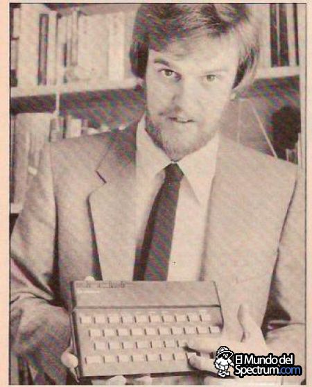
One of the most interesting aspects of Spectrum clones is the inventive ways in which that iconic display output is reproduced. The genuine Spectrum uses a semi-custom chip – the ULA – to integrate the circuitry which generates the video signal. Most Spectrum clones came from Cold War era Eastern Europe, where comparable technology was not readily available to the clone builders. Thus they resorted to replicating the functionality excapsulated in the ULA using individual logic chips. To appreciate exactly what an achievement this was, I think it’s worth taking the time to examine what the main characteristics of the Spectrum’s video output are and how it is produced. In so doing we can appreciate the genius of its inventor, Richard Altwasser3.
The Spectrum has a 256 by 192 pixel bitmap screen. While this is nominally the same as its predecessor the ZX81, the approach taken and the effects achieved are radically different. The ZX81’s screen is character-mapped4, limited to drawing only a predefined set of glyphs5. It uses a variable-sized area of RAM – the DFILE – to store 25 lines of up to 32 characters. When it is time to draw these to the screen, the bitmap representation of these characters are looked-up in ROM and passed to a shifter, which outputs them pixel-by-pixel. All of this is done by the Z80 CPU, taking up approximately 80% of the available processing time each video frame. In contrast, the Spectrum allocates 6144 bytes of RAM as permanent display memory, able to display any kind of bitmap graphics. Responsibility for outputting this data to the video display was taken away from the Z80 and given to custom circuitry, allowing the CPU to dedicate 100%6 of its time to running programme code.
But what would give the Spectrum its distinct visual style – and indeed earn it the ‘Spectrum’ name – was the addition of colour. To achieve this, each 8x8 pixel cell on screen was assigned an attribute byte, containing independent foreground and background colours. These provided a memory-efficient means of adding colour, using just an extra 768 bytes of RAM, stored directly after the bitmap data. The approach was innovative, earning Altwasser a patent on the technique78. It is responsible for the iconic colour clash, and for a few other eccentricities of the video circuitry which any Spectrum clone would have to recreate.
The following description of how the Spectrum’s video signal is generated is taken wholesale from Chris Smith’s book How to Design a Microcomputer9. Any errors introduced while over-simplifying it are entirely mine.
Generating a video signal is, at heart, a matter of counting. The PAL10 signal which the Spectrum produces11 consists of 50 312-line frames every second. The video subsystem is driven by a 7Mhz clock, ticking 448 times per line. Both the vertical line count and the horizontal column count use 9-bit counters.
For simplicity, the vertical counter starts at the point the first line of the Spectrum’s screen is output and counts the 192 lines. It then counts 56 lines for the bottom border, the equivalent of 12 lines for the vertical blank while the electron beam is travelling back to the top of the screen, and finally another 56 lines for the top border, before resetting the count to 0 and starting again. Likewise, the horizontal counter begins with the first column of the Spectrum’s 256-column screen, followed by 64 columns for the right border, the equivalent of 96 columns while the electron beam moves back to the left of the screen, and finally 32 columns for the left border. This means that while the vertical counter is in the range 0-191 and the horizontal counter is in the range 0-255 they together give the screen coordinate of the pixel which is being output.
Of course it isn’t quite as simple as that. Firstly, pixels are stored in memory as the bits within a byte. Before they can be shifted one-by-one into the video output, the byte containing them needs to be fetched. Secondly, the monochrome pixel data needs to be combined with the colour information stored in the attribute data. Since attribute data has a horizontal resolution of the same 8 pixels, we can see that before any run of 8 pixels can be output, the video subsystem needs to fetch two bytes from display memory: one containing the pixels and the other containing the colour attributes. From this stems two further idiosyncrasies of the Spectrum’s design. The first is contention, the possibility that both the video subsystem and the CPU will need to access the display memory at the same time. This is arbitrated at the level of the entire lower 16K block of RAM containing the display memory. In these cases the video subsystem takes priority, removing the clock signal from the CPU while it retrieves the data it needs to keep the video signal flowing.
The second idiosyncrasy should be familiar to anyone who has sat and waited while a Spectrum game loads from tape, although they may not have be aware of what exactly they were seeing. Anyone who has ever tried to program bitmap graphics on the Spectrum, however, will be painfully aware of what is going on.
Here we are watching data being loaded from tape straight into the Spectrum’s display memory. First the bitmap data, and then finally the attributes. The data is being loaded linearly but the lines do not appear on the screen in the order one would naively expect. The reason for this is that the Spectrum’s display memory is not laid out in a strictly linear fashion. And the reason for that is efficiency.
The diagram below12 shows how the horizontal and vertical counters maintained by the video subsystem – and thus the coordinates of each pixel – relate to the address of the corresponding bitmap data in RAM. The display memory begins at $4000 in the Spectrum’s memory map, but from the point of view of the video subsystem, which can only see the lower 16K, it begins at $0.
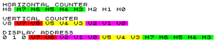
The horizontal component of the address is easily comprehended. The lower 3 bits – H2-H0 – are ignored since we are dealing with byte memory addresses, each containing 8 pixels. H8 is ignored because once the counter passes 256 we are past the screen and into the borders. The remaining 5 bits – H7-H3 – give us 32 bytes per screen line.
The vertical component is more involved. It helps to imagine the screen as divided into 3 equal parts, with each part consisting of 64 lines or 8 character rows, where each character is 8 lines tall. Thus bits V5-V3 index a character row within a screen part and V2-V0 index a line within a character row. But why are they arranged as they are in the address, with the row index before the line? One benefit of this layout is that in order to increment the address pointer to the next line – as one might if you were writing a glyph into a character cell – you need only increment the high byte of the address, an efficient operation on the Z80. But this is likely just a happy side-effect of Altwasser’s real intent.
To understand what is being optimised here, it’s necessary to know a little about DRAM memory chips. The lower 16K of RAM containing the display memory in the Spectrum was made up of eight 6114 chips. Each had a 14-bit – 16K – address space and was responsible for maintaining 1 bit of information. Due to both their internal architecture and the limitations of their packaging, the 14-bit address space was divided into a 7-bit row and 7-bit column address. To select a particular bit to read or write, the system puts the row address on to the chip’s 7 address pins, followed by the column address. This setup takes a certain amount of time. To aid efficiency, DRAM also supported ‘page mode’13, where the row address would be held constant while the column was changed, speeding the read/write setup time.
The Spectrum’s video generation circuitry makes use of DRAM page mode to make fetching the byte of pixel data and its associated attribute byte as efficient as possible. How it achieves this is typically inventive. The orthodox setup would see the row representing the high part of an address, with the column the low part. Thus page mode would allow faster access to data which is close together, such as the bytes of program code. In contrast, the Spectrum’s video subsystem uses the row to represent the low part of the address. Due to the layout of the display memory, this is common between a byte of pixel data and its character cell’s attribute byte.
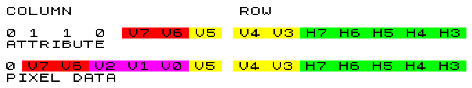
The diagram below shows how the attribute address is derived from the horizontal and vertical counters. Comparing it to the pixel data address we have already met we can see that they share the lower 8 bits, which allows for the page mode access efficiency at the cost of the slightly unusual memory layout.
So why the Spectrum?
The above describes in very rough terms the operation of the Spectrum’s video subsystem. A third party, if they wished to produce a clone which remained compatible with the original, would need to analyse, identify, and replicate this behaviour. And they did. Many separate individuals and groups managed to unlock Altwasser’s secrets and produce their own version, usually assembled from discrete logic chips.
But there remains the question: why? Particularly in the context of Eastern Bloc countries, where most of the cloning happened. Why the Spectrum? Why go to such lengths to copy this particular machine? Nostalgia aside, the Spectrum was far from the best computer of its time. Its killer feature was its low price, which stemmed from its simplicity. It was a Z80, some ROM and RAM, and a semi-custom chip containing the eccentric video subsystem. By way of comparison, a Z80 and memory got you most of the way to a CP/M system, where a custom BIOS14 would allow you to use whatever simple display system you had access to15.
A mark in favour of the Spectrum was the large library of software available for it. But the vast bulk of that – particularly in the later part of its lifetime – was games16. While there’s certainly plenty of evidence now that being introduced to the world of computing via games is an excellent gateway to a career in ‘more serious’ computing17, this was not a given at the time, and would surely have been hard to sell to the kind of authoritarian bureaucrat whose permission would have been required to dedicate resources to the project of cloning the Spectrum. There was an equally large library of software available for CP/M, most of it of a more serious bent and thus more likely to meet with official favour.
I’m sure that as we explore the world of Spectrum clones and the histories of the people who built them we’ll get many different answers to this question. The cleverness of the engineering is certain to play some role. Because ultimately, the genius of Altwasser’s design wasn’t that it was so simple it could be copied and reimplemented by those with access to only more basic technology, it was that it was so efficient, so elegant, and so successful, that they would want to.
Notes
-
No, not Clive Sinclair. ↩
-
https://8bit-museum.de/heimcomputer-2/sinclair/sinclair-scans/scans-zx81-video-display-system/ ↩
-
Not counting the clever display hacks which are now possible. ↩
-
Almost. We’ll cover memory contention between the ULA and the CPU later. ↩
-
Altwasser gladly admits that the approach was a compromise born of the need to keep cost down (eg. https://www.youtube.com/watch?v=4ABg_YWF4YY), but such constraints breed creative solutions. ↩
-
‘Phase Alternating Line’ https://en.wikipedia.org/wiki/PAL ↩
-
We’ll focus only on PAL here. See How to Design a Microcomputer for discussion of the differences in the NTSC variant. ↩
-
This diagram was at least subconsciously inspired by the one shown in this tutorial. ↩
-
https://en.wikipedia.org/wiki/Dynamic_random-access_memory#Page_mode_DRAM ↩
-
Here I’m treating the CP/M BIOS as a simple hardware abstraction layer. ↩
-
Yes, I’m ignoring that CP/M is primarily intended to be used with floppy drives. There were cassette-based versions18 – including for the Spectrum – and it is not uncommon to see it as an option for Eastern Bloc Spectrum clones. ↩
-
cf. “Jet Set fucking Willy!” ↩
-
See for example the number of prominent members of the UK’s computer game industry who credit the Spectrum with their entry into the field. ↩
-
https://retrocomputing.stackexchange.com/questions/6281/cp-m-without-floppy-drive ↩